Logic Charts
Links below each object block provide information on the associated component object:
| Device | Object | Logic I/O | Operation |
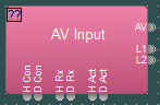
| AV Input |
|
6 Logic Outputs - 3 for HDMI status and 3 for Display Port Status | Logic 1 on H Con - HDMI connected Logic 0 on HI Con - HDMI not connected Logic 1 on D Con - DisplayPort connected Logic 0 on D Con - DisplayPort not connected Logic 1 on H Rx - HDMI receiving frames Logic 0 on H Rx - HDMI not receiving frames Logic 1 on D Rx DisplayPort receiving frames Logic 0 on D Rx DisplayPort not receiving frames Logic 1 on H Act - HDMI is active Logic 0 on H Act - HDMI is not active Logic 1 on D Act - DisplayPort is active Logic 0 on D Act - DisplayPort is not active. |
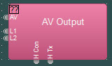
| AV Output |
|
2 Logic Outputs - 2 for HDMI status | Logic 1 on H Con - HDMI connected Logic 0 on H Con - HDMI not connected Logic 1 on H Tx - HDMI Transmitting Logic 0 on H Tx - HDMI not Transmitting |
| Paging Zone |
Paging Zone |
1 Logic Output | Active High when page is active in the zone, low when zone is not being used for paging. |
| Mute Control |
|
1 logic input and output per audio channel, up to 16 channels per block (56 ganged) | Logic input 1 causes audio channel to mute. Logic input 0 causes audio channel to un-mute. |
| Level Inc/Dec |
|
1 logic input for level up (+) on each audio channel. 1 logic input for level down (-) on each audio channel. Up to 32 audio channels per block (64 ganged) | Logic 1 input to (+) causes level to ramp up. Logic 1 input to (-) causes level to ramp down. Optional: Disable ramping Transition from logic 0 to 1 on (+) causes audio to increment up. Transition from logic 0 to 1 on (-) causes audio to increment down. |
| Preset Button |
|
1 logic input per preset, up to 10 presets per block | Transition from logic 0 to logic 1 triggers preset to recall |
| TI Dialer |
|
19 logic inputs and 1 logic output | Transition from logic 0 to logic 1 on input 1 to 16 causes the associated speed dial number to be dialed. Transition from logic 0 to logic 1 on Redia input causes the last number to be redialed. |
| HD-1 |  |
1 Mute 4 Outputs | Mute logic output is a latching signal that follows the state of the mute button of the HD-1 hardware. Soft button logic outputs 1 through 4 will trigger a logic 1 for 200ms when the corresponding HD-1 hardware soft button is pushed. |
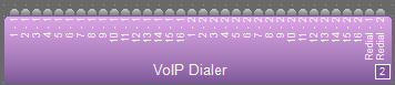
| VoIP Dialer |
|
34 logic inputs (17 for each line) | Transition from logic 0 to logic 1 on input 1-x to 16-x causes the associated speed dial number in the corresponding line to be dialed. Transition from logic 0 to logic 1 on Rdl-x input causes the last number to be redialed in the corresponding line. |
| Gating Auto Mixer |
|
1 logic output per input channel, up to 256 channels per block | Logic output normally Logic 0 Switches to Logic 1 as long as corresponding input channel is gated on. Optional: Behavior of logic output may be inverted in control dialog. |
| Room Combiner |
|
1 logic input per partition plus 5 source selection inputs (4 sources + Off) per room, up to 32 rooms (58 partitions) per block 1 logic output per partition plus 5 source selection outputs (4 sources + Off) per room, up to 32 rooms (58 partitions) per block | Logic 0 on partition input causes partition to remain open. Logic 1 on partition input causes partition to remain closed Transition from logic 0 to 1 on source inputs selects the corresponding audio source (or Off) for the corresponding room Logic 0 on partition output indicates partition is open Logic 1 on partition output indicates partition is closed Logic 1 on any source selection output indicates that source (or Off) is selected for that room |
| Source Selection |
|
1 Logic input per channel, up to 32 channels 1 Logic output per channel, up to 32 channels | Transition from logic 0 to 1 on logic inputs selects the corresponding audio source Logic outputs normally logic 0. Logic 1 on logic output indicates corresponding audio source is selected |
| Ducker |
|
1 logic input and 1 logic output | 1 on logic input causes program audio to duck and logic output to be 1. 0 causes program to un-duck. Audio signal exceeding threshold on sense input causes logic output to be 1. Audio signal below threshold causes logic output to be 0. Optional: Behavior of logic control may be inverted in control dialog. |
| AGC |
|
1 logic output | A logic 1 indicates the AGC is applying or reducing gain In Speech Mode, a logic 1 indicates Speech is being detected |
| DTMF Decode |
|
17 logic outputs | Logic outputs 1 thru D pulse high for 250msec when the corresponding DTMF tone is detected. Logic output Any pulses high for 250msec when any DTMF tone is detected. |
| TI Control / Status |
|
2 logic inputs and 10 logic outputs | Logic 1 on HS input picks up the line or “takes off hook”. Logic 0 causes the line to hang up or “Put back on hook” Transition from logic 0 to logic 1 on HF input causes a hook flash. Logic 1 on RI = line is ringing Logic 0 on RI = line is not ringing Logic 1 on DIP = Dialing in progress Logic 0 on DIP = Not dialing Logic 1 on HSS = Off hook Logic 0 on HSS = On hook Logic 1 on DTD = Dial tone detected Logic 0 on DTD = No dial tone Logic 1 on BTD = Busy tone detected Logic 0 on BTD = Busy tone not detected Logic 1 on RTD = Ring tone detected Logic 0 on RTD = No ring tone detected Logic 1 on LR = Line ready Logic 0 on LR = Line not ready Logic 1 on LIU = Line in use Logic 0 on LIU = Line not in use Logic 1 on LI = Line intrusion Logic 0 on LI = No line intrusion Logic 1 on LF = Line fault detected Logic 0 on LF = No line faults |
| VoIP Control / Status |
|
24 logic inputs (two per appearance per line) and 26 logic outputs (two per appearance per line plus 2 per line) | Transition from 0 to 1 on ANS x.y answers the call on appearance x line y Transition from 0 to 1 on END x.y ends the call on appearance x line y Logic 1 on RI x.y indicates appearance x on line y is ringing Logic 1 on LIU x.y indicates appearance x on line y is in use Logic 1 on LR1 (LR2) = Line 1 (2) in line ready mode Logic 0 on LR1 (LR2) = Line 1 (2) in not ready mode |
| Network Command String |
|
1 logic input per command string, up to 32 per block. Logic outputs as defined by the user up to 32 per block. |
Transition from logic 0 to 1 triggers command string to output network port. Logic outputs pulse for 250 ms when expected response string is matched. |
| Serial Command String |
|
1 logic input per command string, up to 32 per block |
Transition from logic 0 to 1 triggers command string to output serial port. |
| Signal Present Meter |
|
1 logic output per meter, up to 32 per block |
Audio signal exceeding threshold on sense input causes logic output to be 1. Audio signal below threshold causes logic output to be 0. |
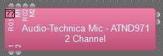
| Audio-Technica Mic |
|
3 logic inputs (per mic, dependant on settings specified in the Initialization dialog), up to 64 per block 1 logic output per channel, up to 64 per block |
Logic 0 on RG = Red LED Logic 1 on RG = Green LED Logic 0 on R = Red LED off (independent of G state) Logic 1 on R = Red LED on (independent of G state) Logic 0 on G = Green LED off (independent of R state) Logic 1 on G = Green LED on (independent of R state) Logic 0 on M = Channel Unmuted Logic 1 on M = Channel Muted Logic 0 on x = Microphone currently Unmuted Logic 1 on x = Microphone currently Muted |
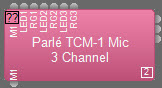
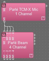
| Parlé Mic |
|
Up to 3 logic inputs (per mic, dependent on settings specified in the initialization dialog) Mute logic may be grouped to a single input Up to 2 Logic output channels (per mic, dependent on settings specified in the initialization dialog) |
Logic 0 on Mx = Channel Unmuted Logic 1 on Mx = Channel Muted Logic 0 on LEDx = LED off Logic 1 on LEDx & Logic 0 on RGx = Red LED Logic 1 on LEDx & Logic 1 on RGx = Green LED Logic 0 on output Mx = Channel Unmuted Logic 1 on output Mx = Channel Muted
Optional for TTM-X only: Logic 0 on output Bx = Channel Logic Low (physical button is not pressed) Logic 1 on output Bx = Channel Logic High (physical button is pressed) |
| Parlé Amp |
|
2 logic outputs for Faults and Warnings | Logic 0 on F = No Fault Present Logic 1 on F = Fault Present Logic 0 on W = No Warning Present Logic 1 on W = Warning Present |
| Parlé Beam |
|
Logic inputs control the individual Beam Mute States
Logic outputs reflect individual Beam Mute States |
Logic 0 = Beam Unmuted Logic 1 = Beam Muted |
| AMP-450P |
|
2 logic outputs for Faults and Warnings | Logic 0 on F = No Fault Present Logic 1 on F = Fault Present Logic 0 on W = No Warning Present Logic 1 on W = Warning Present |
| AMP-450BP |
|
2 logic outputs for Faults and Warnings |
Logic 0 on F = No Fault Present Logic 1 on F = Fault Present Logic 0 on W = No Warning Present Logic 1 on W = Warning Present |
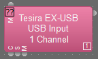
| EX-USB (USB Input) |
|
1 logic input for USB connected state 1 logic input for streaming state 1 logic input for mute synchronization state |
Logic 0 on M = USB Host Unmuted Logic 1 on M = USB Host Muted Logic 0 on C = USB Host Not Connected Logic 1 on C = USB Host Connected Logic 0 on S = USB Host Not Streaming Logic 1 on S = USB Host Streaming |
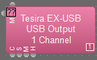
| EX-USB (USB Output) |
|
1 logic output for USB connected state 1 logic output for streaming state 1 logic output for mute state |
Logic 0 on M = USB Audio Output Unmuted Logic 1 on M = USB Audio Output Muted Logic 0 on C = USB Output Not Connected Logic 1 on C = USB Output Connected Logic 0 on S = USB Audio Output Not Streaming Logic 1 on S = USB Audio Output Streaming Logic low on H = USB Host is On Hook (Idle, not in an active call, or on hold) Logic high on H = USB Host is Off Hook (Active call) |
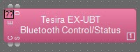
| EX-UBT (Bluetooth) |
|
2 logic inputs for Bluetooth state (enable/disable) 2 logic outputs for Bluetooth status |
Logic 0 on E = Bluetooth Disabled Logic 1 on E = Bluetooth Enabled Logic 0 on D = Bluetooth Not Discoverable Logic 1 on D = Bluetooth Discoverable Logic 0 on C = Bluetooth Not Connected Logic 1 on C = Bluetooth Connected Logic 0 on S = Bluetooth Not Streaming Logic 1 on S = Bluetooth Streaming |
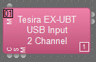
| EX-UBT (USB Input) |
|
1 logic input for USB connected state 1 logic input for streaming state 1 logic input for mute synchronization state |
Logic 0 on M = USB Host Unmuted Logic 1 on M = USB Host Muted Logic 0 on C = USB Host Not Connected Logic 1 on C = USB Host Connected Logic 0 on S = USB Host Not Streaming Logic 1 on S = USB Host Streaming |
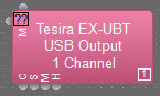
| EX-UBT (USB Output) |
|
1 logic output for USB connected state 1 logic output for streaming state 1 logic output for mute state |
Logic 0 on M = USB Audio Output Umuted Logic 1 on M = USB Audio Output Muted Logic 0 on C = USB Output Not Connected Logic 1 on C = USB Output Connected Logic 0 on S = USB Audio Output Not Streaming Logic 1 on S = USB Audio Output Streaming Logic low on H = USB Host is On Hook (Idle, not in an active call, or on hold) Logic high on H = USB Host is Off Hook (Active call) |
| USB X Input |
|
1 logic input for USB connected state 1 logic input for streaming state 1 logic input for mute synchronization state |
Logic 0 on M = USB Host Unmuted Logic 1 on M = USB Host Muted Logic 0 on C = USB Host Not Connected Logic 1 on C = USB Host Connected Logic 0 on S = USB Host Not Streaming Logic 1 on S = USB Host Streaming |
| USB X Output |
|
1 logic output for USB connected state 1 logic output for streaming state 1 logic output for mute state |
Logic 0 on M = USB Audio Output Unmuted Logic 1 on M = USB Audio Output Muted Logic 0 on C = USB Output Not Connected Logic 1 on C = USB Output Connected Logic 0 on S = USB Audio Output Not Streaming Logic 1 on S = USB Audio Output Streaming Logic low on H = USB Host is On Hook (Idle, not in an active call, or on hold) Logic high on H = USB Host is Off Hook (Active call) |
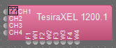
| TesiraXEL 1200 Amplifier |
|
4 logic outputs for Warning 4 logic outputs for Fault |
Logic 0 on F = No Fault Present Logic 1 on F = Fault Present Logic 0 on W = No Warning Present Logic 1 on W = Warning Present |
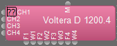
| Voltera D Series Amplifier |
|
1 logic output for mute state. 4 logic outputs for Warning 4 logic outputs for Fault (8 of each on 8 channel blocks) |
Logic 0 on M = Audio Outputs Unmuted Logic 1 on M = All Audio Outputs Muted Logic 0 on F = No Fault Present Logic 1 on F = Fault Present Logic 0 on W = No Warning Present Logic 1 on W = Warning Present |
| Voltera D M Series Amplifier |
|
1 logic output for mute state. 2 logic outputs for Warning 2 logic outputs for Fault (4 of each on 4 channel blocks) |
Logic 0 on M = Audio Outputs Unmuted Logic 1 on M = All Audio Outputs Muted Logic 0 on F = No Fault Present Logic 1 on F = Fault Present Logic 0 on W = No Warning Present Logic 1 on W = Warning Present |
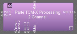
| Parlé Processing Block |
|
2 logic outputs per Mic for Mic Active and AGC. One additional output for Mute Status |
Logic 0 on Mic # Active = Mic Inactive Logic 1 on Mic # Active = Mic Active Logic 0 on Mic # AGC = AGC Inactive Logic 1 on Mic # AGC = AGC Active Logic 0 on Mute Indicator = Mute Inactive Logic 1 on Mute Indicator = Mute Active |


Logic Blocks
| Device | Object | Logic I/O | Operation | |||||||||||||||
| Logic Input |  |
Up to 16 channels | Open on logic input = Logic 1 Closure on logic input= Logic 0 Optional: Behavior of logic control may be inverted in control dialog. | |||||||||||||||
| Logic Output/LED Driver |  |
Up to 16 channels | In Logic mode
Logic 1 on logic output = open Logic 0 on logic input =closure In LED Driver modeLogic 1 on logic output = Up to 24V/500mA Logic 0 on logic input = Short to ground Optional: Behavior of logic control may be inverted in control dialog. |
|||||||||||||||
| Logic Delay |
|
1 logic input and 1 logic output per delay, up to 32 per block | 1 on logic input must be present for specified ON time before logic output changes to 1. 0 on logic input must be preset for specified OFF time before logic output changes to 0. | |||||||||||||||
| OR Gate |  |
2-32 logic inputs and 1 logic output | 1 at either or both logic inputs causes a 1 at logic output. Otherwise, logic output is 0.
|
|||||||||||||||
| AND Gate |  |
2-32 logic inputs and 1 logic output |
1 at both inputs causes a 1 at logic output. Otherwise, logic output is 0.
|
|||||||||||||||
| NOT Gate |  |
1 logic input and 1 logic output per gate, up to 32 per block | 1 at logic input causes a 0 at logic output. 0 at logic input causes a 1 at logic output.
|
|||||||||||||||
| NOR Gate |  |
2-32 logic inputs and 1 logic output | 0 at both logic inputs causes a 1 at logic output. Otherwise, logic output is 0. (Logically the same as an OR gate followed by a NOT gate.)
|
|||||||||||||||
| NAND Gate |  |
2-32 logic inputs and 1 logic output | 1 at both logic inputs causes a 0 at logic output. Otherwise, logic output is 1. (Logically the same as an AND gate followed by a NOT gate.)
|
|||||||||||||||
| XOR Gate |  |
2-32 logic inputs and 1 logic output | 1 at either but not both logic inputs causes a 1 at logic output. Otherwise, logic output is 0.
|
|||||||||||||||
| Flip Flop Gate |  |
1 logic input and 1 logic output per gate, up to 32 per block | 0 to 1 transition at logic input causes logic output to toggle from its present state to the opposite state. | |||||||||||||||
| Logic Meter |  |
1 logic input per meter, up to 32 per block | Logic 1 on input node turns corresponding indicator on Logic 0 on input node turns corresponding indicator off | |||||||||||||||
| Logic State |  |
1 logic output per state, up to 32 per block | Setting a State On causes the corresponding logic output to be 1. Setting the State Off causes the corresponding logic output to be 0 | |||||||||||||||
| Logic Selector |  |
1 logic input and output per state, up to 32 per block | Setting a State On causes the corresponding logic output to be 1. Setting the State Off causes the corresponding logic output to be 0. Outputs mutually exclusive, only one can be high at a time. | |||||||||||||||
| Logic Pulse |  |
1 logic input and 1 logic output per channel, up to 32 per block | A rising-edge logic value on an input will trigger a pulse to start on that channel’s output. If a pulse is already running when an input trigger occurs, it will be stopped instead of started. | |||||||||||||||
|
Logic Sequence |
 |
1 logic input and 1-32 logic outputs | Transition from logic 0 to logic 1 on the input will start (or stop if already running) the configured sequence. All outputs are participants of the sequence and will behave as configured by the user. | |||||||||||||||
| Fan-In OR Pulse | 2-32 logic inputs and 1 logic output | Transition from logic 0 to logic 1 on any of the inputs generates a 150ms logic pulse on the output. A de-bounce delay of 300ms is used after the initial pulse |