Voltera Amplifiers - D & DM Series
Use the Voltera - D or DM series block and the associated control dialog to match and configure loudspeakers with amplifiers in a system.
Follow the links below to jump to another topic:
Initialization Dialog
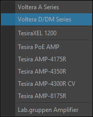
From the amplifier section of the I/O control blocks drop-down menu located on the audio object toolbar, select Voltera Series and drop the Voltera control block onto the partition.
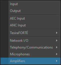
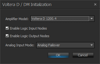
Select an amplifier model from the initialization window.
Use the Enable Logic Input Nodes and Enable Logic Output Nodes checkboxes to utilize logic functionality on Voltera D-series blocks.
Use the Analog Input Mode drop down menu to select a mode for the block:
- Analog Failover - Automatically routes audio to analog channels upon loss of digital media. Additional guidance is available in the Input Priority Routing section.
- Include Analog Input Block - places the Analog Input block (representing the rear panel inputs of the Voltera D unit) separate from the Voltera D block allowing for customization of usage. This option will remove the Analog failover option from the Input Priority Routing section of the Mixer page control dialog.
Note: Analog Failover may also be selected in scenarios where failover is not desired, select the "none" option from the drop-down menu in the Input Priority Routing section of the Mixer page control dialog.
DSP Block Representation
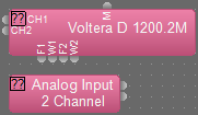
If enabled, Voltera D blocks may have logic input for Mute All functionality, the rear panel Mute All input takes precedence, and output ports included for indicating channel faults and warnings.
2 Channel
2 channel blocks include 1200.2M, 2400.2M, and 4800.2M models:


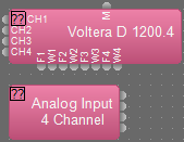
4 Channel
4 channel blocks include 600.4M, 1200.4, 1200.4M, 2400.4, 2400.4M, 4800.4, and 48004M models:


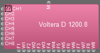
8 Channel
8 channel blocks include 1200.8 and 2400.8 models:

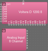
Note: Once a block is placed, right clicking on the block and selecting Edit Block Parameters to switch between a Voltera D and Voltera DM models.
Equipment Table
Voltera blocks may be added to the Equipment Table, with card information populated.
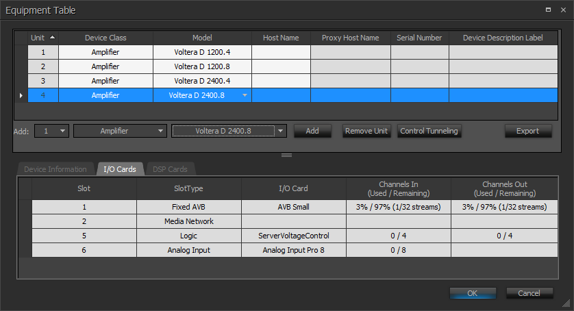
Port Modes
Port Mode options available from the Network Settings section of the Device Maintenance window include:
- Dedicated Control and Media, Port 1 and Port 2 supports a control connection for device discovery, management, and programming. Port 2 also supports network media in this mode.
- Converged Control and Media, Port 1 supports both control and network media in this mode.
- Redundant Dante, Port 1 supports control and primary network media while Port 2 supports secondary network media in this mode.
For additional details about port mode settings see the Voltera D and DM - Tesira Configuration article on Cornerstone.
Control Dialog
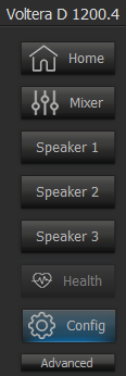
Double click the DSP block to use the control dialog and manage settings via the Home, Mixer, Configuration, Health, and up to eight Speaker pages.
Advanced Configuration
While Configuration is selected, use the Advanced button to access Operation Modes and General Options.
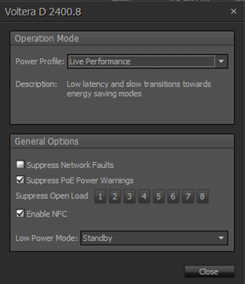
Power Profile:
- Live Performance - The default selection, Low latency and slow transitions towards energy saving modes.
- Live Green - Low latency and more aggressive transitions towards energy saving modes.
Suppress Network Faults: When this is checked it will not generate any faults/warnings for network related issues. This feature is primarily used for stand alone Voltera units (A unit without a connection to Tesira is considered stand alone).
Suppress PoE Power Warnings: When this is checked it will not generate a warning when it doesn't have PoE power present on network port 1.
Suppress Open Load: Allows for the selection of specific channels for open load suppression.
Enable NFC: When this is checked the device's configuration details, status information, and fault codes will be NFC readable. For additional information, see the Voltera D Series Hardware Installation and Setup Guide or download the Workplace Tools app. Available for Apple iOS® and Google Android®.
Low Power Mode: May be set to Standby or Sleep. More details available under the Sleep and Standby section.
Configuration
Use the Configuration page to name speakers and outputs for the loudspeaker channels, to create, edit, and save custom loudspeaker files, as well as view and customize the power usage.
Note: Voltera configuration page is only editable while offline.
| Callout | Description | Range |
| 1 | Letter indicators for loudspeaker channels. Each letter corresponds to the same letter on each other page associated with the selected block. | |
| 2 | Input Label text field for naming a speaker for the loudspeaker channels. This field cannot be empty, has a 40 character limit. | |
| 3 | Loudspeaker file creation and management icons. See Loudspeaker Files for additional details | |
| 4 | Loudspeaker Mode drop down menu is populated with power modes. This alters Power and Z values under the Output Mode. | |
| 5 | Parallel Quantity, set the number of parallel Loudspeakers for power management. This alters Power and Z values under the Output Mode. | 1 to 999 |
| 6 |
Power Adjust, a dB reduction that is either automatically applied when you select a loudspeaker profile that overbooks the channel or can be manually adjusted for designs that do not require the max SPL from the loudspeaker and the user wants to provision more power to other channels. A yellow border will display around the Power and Z controls when power adjust is enacted. |
-12.0 to 0 dB |
| 7 | Displays the maximum power a channel is configured to use. | |
| 8 | Z, displays nominal impedance. | |
| 9 | Output Label text field for naming a speaker for channel outputs. This field can be empty, has a 40 character limit. |
Power Usage
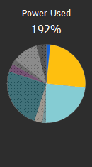
Load percentage is displayed on the right of the configuration page and each loudspeaker will be visualized as a colored slice of the chassis headroom pie chart.
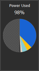
Note: An amplifier cannot exceed 200% and if a loudspeaker is selected for a channel that would exceed that value a warning is displayed and that channel will not be matched with the loudspeaker.
Loudspeaker Files
Users may create, edit, select, save, or remove loudspeaker files
Note: Audio will not pass through a channel in a system without a loudspeaker for that channel.
Create Loudspeaker
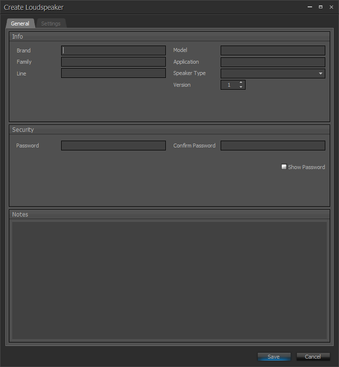
Use the loudspeaker icon to create custom loudspeaker files.
The Brand and Model fields are required, all other attributes within the General Tab are optional. Each attribute can consist of up to 40 characters. The Notes field allows for up to 1000 characters.
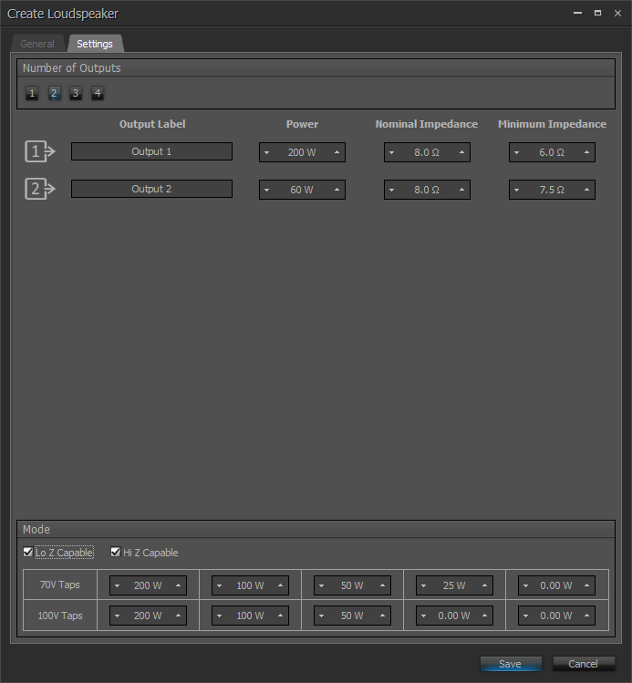
From the Settings Tab a user may determine the of Number of Outputs, Output Label, Power, Nominal Impedance, and Mode. The Power field is required, all other attributes are optional. Select Save to create and apply the loudspeaker file. The number of available outputs is determined by how many of the successive channels are provided in the current block for the loudspeaker to be applied to. Selecting more than one output will create a multi-way speaker, details below.
Use the Lo Z mode selection to use the Nominal Impedance. Hi Z mode selection requires wattage be provided for at least one tap. A maximum of 10 taps are allowed, five per voltage. Entering a value into the first 70V tap field populates the first four 70V taps and the first three 100V taps. The pre-populated fields may be customized individually.
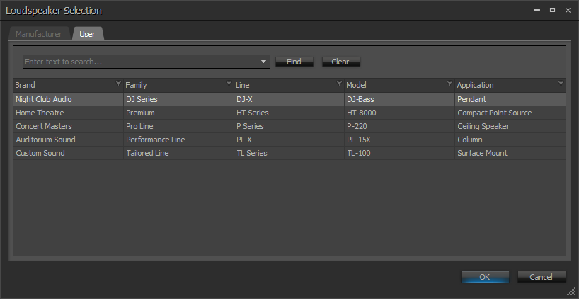
User created loudspeaker files should be saved under C:\User\"current user"\Documents\Biamp\Loudspeakers folder. Loudspeaker files saved in this location will be shown within the User tab of the Loudspeaker Selection dialog. Files will be saved with a .tsp extension by default.
Multi-Way Loudspeakers
Create Multi-Way Loudspeaker files that utilize multiple channels of amplification to power a single loudspeaker.
During Loudspeaker file creation, use the Number of Outputs section of the Settings Tab to set multiple channels of amplification outputs to power a single loudspeaker. Creating a multi-way loudspeaker uses the selected number available channels below the selected channel to create the multi-way speaker. For this reason, the bottom channel of an amplifier, channel D for a 4 channel amplifier and channel H for an 8 channel, may not be used to create a multi-way speaker.
Multi-way loudspeakers use common Loudspeaker Input processing, which is routed to each of the individual Loudspeaker Output channels for speaker specific processing. (e.g. crossover filtering)
Note: In a Multi-way loudspeaker set-up the Mixer page will remove output channels to represent the common Loudspeaker Input. On the Home page, the input mute will mute all outputs of the loudspeaker whereas the output mute will only mute that specific output.
Loudspeaker Selection
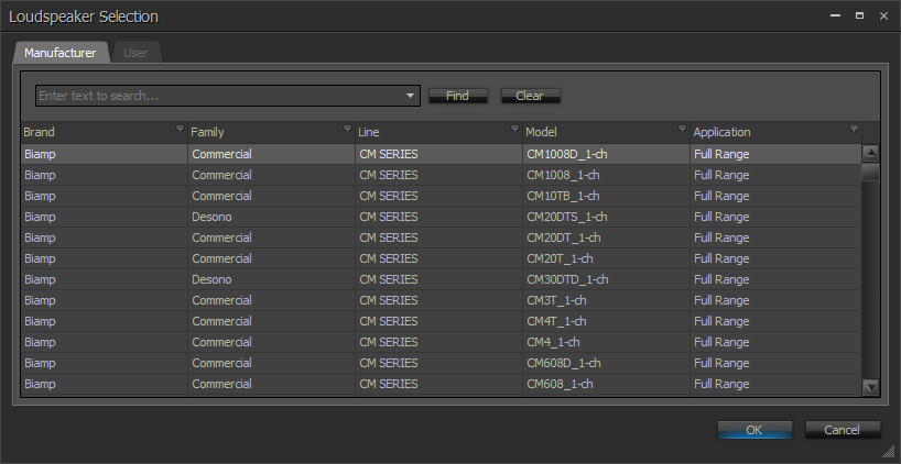
Use the select a loudspeaker icon to select a manufacturer or user loudspeaker file.
The Loudspeaker Selection dialog is populated with Loudspeaker files from a local file system. The manufacturer developed loudspeaker files will be located under C:\Users\Public\Public_Documents\Biamp\Tesira\Loudspeakers folder.
Note: To provide the most efficient DSP utilization all Biamp manufacturer loudspeaker files are provided in a locked state.
Saved user created loudspeaker files are available under the User tab.
Channels with a Loudspeaker file configuration may be saved using the save icon or edited by using the edit the loudspeaker icon
. A channel may be set as unconfigured by using the remove the selected loudspeaker icon
. Setting a channel as unconfigured will only remove the configuration from the block, any saved changes will remain on the file system. Any unsaved changes will be lost.
Home
Use the home page to make adjustments to User Input for room EQ, Loudspeaker Input to preform any processing or pre-crossover, Loudspeaker Output for tuning specific to an output, as well as naming speakers and outputs.

Note: The manufacturer prepared loudspeaker files Loudspeaker Input section and Loudspeaker Output section, by default, cannot be edited.
| Callout | Description | Range |
| 1 | Input Labels and letter indicators for loudspeaker channels. | |
| 2 | Input Label text field for naming a speaker for the loudspeaker channels. This field cannot be empty, has a 40 character limit, and remains changeable while the system is connected. | |
| 3 | Summary of the user input applied EQ curve and input meter. | |
| 4 | User input adjustable level control (dB) | -100.0 to 12.0 dB |
| 5 | User input adjustable delay control (ms) | 0 to 2000 ms |
| 6 | User input mute and polarity toggles. | |
| 7 | Summary of the loudspeaker input applied EQ curve and Dynamic EQ indicator lights. Dynamic EQ lights are blue when there is any, cut or boost, activity within the band. | |
| 8 | Summary of the loudspeaker output applied EQ curve and output meter. | |
| 9 | Loudspeaker output adjustable level control (dB) | -100.0 to 12.0 dB |
| 10 | Loudspeaker output adjustable delay control (ms) | 0 to 20 ms |
| 11 | Loudspeakers Output Mute, limit indicator, and status indicator. The limit indicator remains grey until limiting is applied, then it will display red. The status indicator will display grey while offline, green while online, and yellow or red (depending on the severity of the fault) when faults are present. Text will display next to the indicator naming the type of fault. | |
| 12 | Output Label text field for naming outputs. This field can be empty, has a 40 character limit, and remains changeable while the system is connected. | |
| 13 | Status panel shows indicators of the operation status of the amplifier. |
Status Panel
Status indicators will display a summary of the operational status of the Voltera D, indicating when any issues are present. Text will display next to the indicator naming the type of fault. When more than one fault is active, the fault with the highest priority is displayed. Mains V is displayed in Volts, Mains I is displayed in Amps, Temperature is displayed as a percentage. Mains V and I should be monitored in accordance with regional standards in mind. Temperature cannot exceed 100% and nearing this threshold should be understood as a problem with the device or its environment.
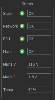
- State - summarizes the general state of the Voltera D unit (Offline / Online).
- Network - summarizes the network connection status.
- PSU - summarizes issues relating to the Power Supply Unit within the Voltera D unit. Such as temperature limits being exceeded, and fan stuck.
- Mains - summarizes issues observed in the mains power supply into the Voltera D unit. Such as under-voltage and over-voltage conditions.
- Channel Faults - faults specific to a single channels are displayed within the Loudspeaker Output section of the Home page. Such as Short Circuit, No Load, and excessive temperature conditions.
Network Port 1 should be used for Control and Network Port 2 for Media, in a system based upon a Separated Network topology.
Note: Voltera D(M) units may use PoE power (supplied on Network Port 1 only) to maintain settings, and enable quick recovery of audio when the mains supply is lost. Audio from the device, including from the analog inputs, is not available while the unit is powered from PoE.
Mixer
The mixer page has an input meter for each input source as well as a pink noise generator mute toggle and level adjustment. Each input meter has a corresponding detailed input meter, Digital / Analog settings adjustment, and a copy settings button on the right side of the page. Each available output may be selected in relation to an input similar to using a Matrix Mixer:

| Callout | Description | Range |
| 1 | Input selection, Digital / Analog failover selection toggle, Input Priority Routing drop-down, input meter for each input source, and pink noise level mute toggle and adjustment | -100.0 to 36.0 dB |
| 2 | Letter indicators and meters corresponding to the loudspeaker channels displayed on the Home page | |
| 3 | Detailed input meter | |
| 4 | Digital Input trim adjustment setting, Analog Trim and Delay settings, and copy settings to all channels |
-100.0 to 12.0 dB 0 to 5.00 ms |
Note: Each input output pairing has a level adjustment available by right clicking on the button at the intersection of the input row and output column.
Input Priority Routing
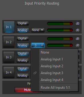
Allows the user to select the priority routing of physical input in a failover scenario. By default, each channel will be set as 1:1 priority routing. Digital is routed from the port on the software block, Analog is routed from the back panel of the device (analog inputs). Configure the routing as desired for each channel using the Digital / Analog toggle and analog routing drop down. Choosing an Analog Input option from the drop-down on a channel will select that input as the failover for the input on the current channel. In scenarios where failover is not desired, choose the analog toggle option and select the "none" option from the drop-down menu.
Loss of digital media on any channel will trigger failover for all channels configured with an analog failover channel. For additional information, refer to the Voltera D Amplified Loudspeaker Controllers - Tesira Configuration article on Cornerstone.
Note: The dB meter to the right of the analog or digital toggle will always display audio exclusively for that channel. If a failover has occurred and audio has been routed to the input selected from the drop-down, the meter will not display any audio because it has failed over to the selected source.
If Include the Analog Input Block checkbox was selected from the Initialization window when placing the Voltera D block, the analog failover toggle and drop-down menu will not be available.
Speaker
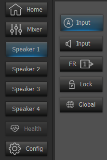
Each speaker page is composed of at least five sub pages; User Input, Loudspeaker Input, Loudspeaker Output, Lock, and Global. Multiple Loudspeakers Output pages will be available for multi-way speakers.
Note: Speaker page user EQ is based on minimum phase raised cosine EQ curves rather than classical EQ to emulate analog EQ. The key difference is that user EQ are more narrow in the frequency range that they effect. The Q value is converted into bandwidth. For each Speaker page with a User Input meter, the meter is situated before the level slider in the signal chain and thus changes to the level slider are not reflected in this meter.
User Input
User Input page features a mixer output display, and adjustable level, and delay controls with mute and polarity toggles that correspond to the User Input controls on each other page. This page also includes EQ filter band options and chart as well as thermal, program, and peak limiter meters. The User Input page is used for room tuning. Limiter attributes can be set from the Loudspeaker Output page.
Note: The copy and paste functions are located in the EQ filter control for User Input, Loudspeaker Input, and Loudspeaker Output pages.Copy and paste captures all bands, the paste feature is only supported between similar pages: i.e - User Input filter bands can be pasted to other User Input pages, and Voltera D-Series bands cannot be copied to Voltera A-Series. Copy and paste is not available online.
Loudspeaker Input
Loudspeaker Input features adjustable level controls with mute toggle that correspond to the User Input controls on the Home page. Loudspeaker Input includes EQ filter band options and chart, a bypass toggle, a Voltera FIR Filter, as well as a Dynamic EQ page button and bypass toggle.
While the Dynamic EQ button is selected the Dynamic EQ display replaces the standard EQ filter display on the loudspeaker input page. The Dynamic EQ display has a 3-band filter selection, and each band has adjustments for center frequency (HZ), gain (dB), Q, and threshold (dBu). Each band also has a bypass toggle as well as threshold mode and transition drop down menus.
Dynamic adjust (Gain), positive or negative, set in the specific frequency band will be applied to the signal proportionally to the value of the signal that exceeds the threshold value.
Dynamic processing may be set to happen before or after reaching the threshold value. If the band is set to activate when the signal exceeds the threshold value, there will be no processing when the signal is lower than the threshold value. If the band is set to activate when the signal is lower than the threshold value, there will be no processing when the signal exceeds the threshold value.
The Transition drop down menu sets how the transition between the non-compression and compression states is made. The Hard setting indicates a quick switch to compression as soon as the signal level exceeds the threshold value. The Soft setting indicates a softer and slower transition to compression when the threshold is exceeded.
Loudspeaker Output
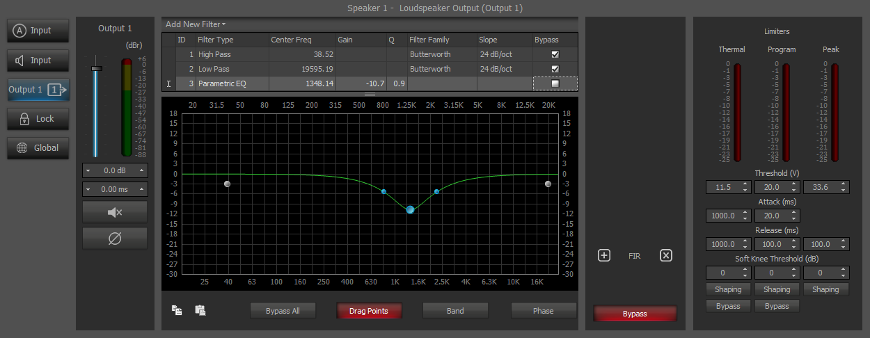
The Loudspeaker Output page features adjustable level and delay controls with mute and polarity toggles that correspond to the Loudspeaker Output controls on the Home page. This page includes EQ filter band options and chart, a Voltera FIR Filter, and has adjustment levels and bypass toggles for Thermal, Program, and Peak Limiters. Each limiter has a Side Chain EQ that is accessible while the Shaping button is selected for that limiter.
Note: The first two bands cannot be deleted and are intended to be used as a crossover, and thus allow a greater slope than other bands. Threshold is presented in volts (V) and Soft Knee Threshold is presented in decibels (dB) in the Limiters section.
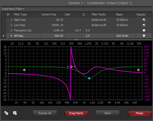
The Filters shown on the User Input, Loudspeaker Input, Loudspeaker Output allow the selection of All Pass Filter bands. For All Pass Filter bands the Phase button must be enabled to see any effect.
Note: All Pass Filter bands are not available within the Voltera Limiter Shaping or existing Uber Filter block. 1st and 2nd Order All Pass filter bands are available. All Pass Filters are specified by Center Frequency and Order. Only 2nd order filter bands also allow for adjustment of Q, either via drag points along the plot or via the text field in the table.
Lock page
Use the Lock page to password protect access to subsections of the loudspeaker settings including input equalization, input dynamics, output equalization, and output limiters. A locked section is presented in a read only state whereas a hidden section keep fields blocked from view. Once a correct password has been accepted in the type line under Security, each section may be locked or unlocked and may be made visible or hidden. While a loudspeaker section is locked or hidden, no changes may be made.
Global
The Global page shows the EQ curves from each of the different pages overlaid on the same panel chart. Each page has a toggle below the chart with a color indicator bar displayed above that is associated with the line on the graph displaying information about that page.

Note: The Loudspeaker Output EQ color indicator is displayed next to the output it corresponds to on the left. For multi-way speakers each output will be displayed with its own color indicator.

Input Gain - when selected any input gain will be applied to the EQ curves.
Output Gain - when selected any output gain will be applied to the EQ curves.
Note: The loudspeaker input, Dynamic EQ, and loudspeaker output buttons will follow the lock page visible button selection.
Health
The Health page is split into Channel and System. Each view displays the most recent 3-hour range, the slider bar at the base of the graph may be use to view activity beyond this range. Each view has a Reset Zoom button, in the lower right, to return to the most recent 3-hour range view and a refresh button and time updated in the lower right of the panel. The Health page will remain inaccessible until the device is online.
The health data log will persist after a reboot but will be cleared after a factory reset. Only the last 24 hours of data will display, and only if the device is configured with a layout within that time. An unconfigured device won't record the health parameters.
System
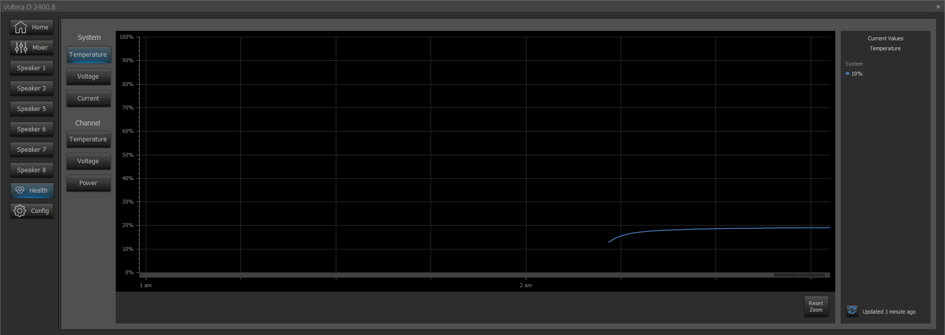
System Temperature is displayed as a percentage. Temperature cannot exceed 100% and nearing this threshold should be understood as a problem with the device or its environment.
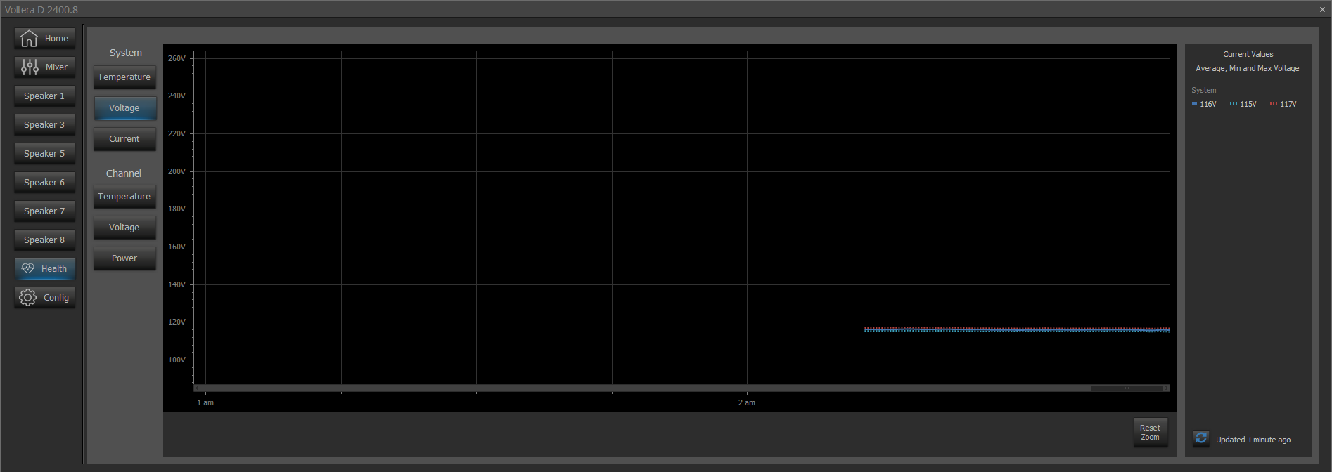
System Voltage is displayed in Volts.
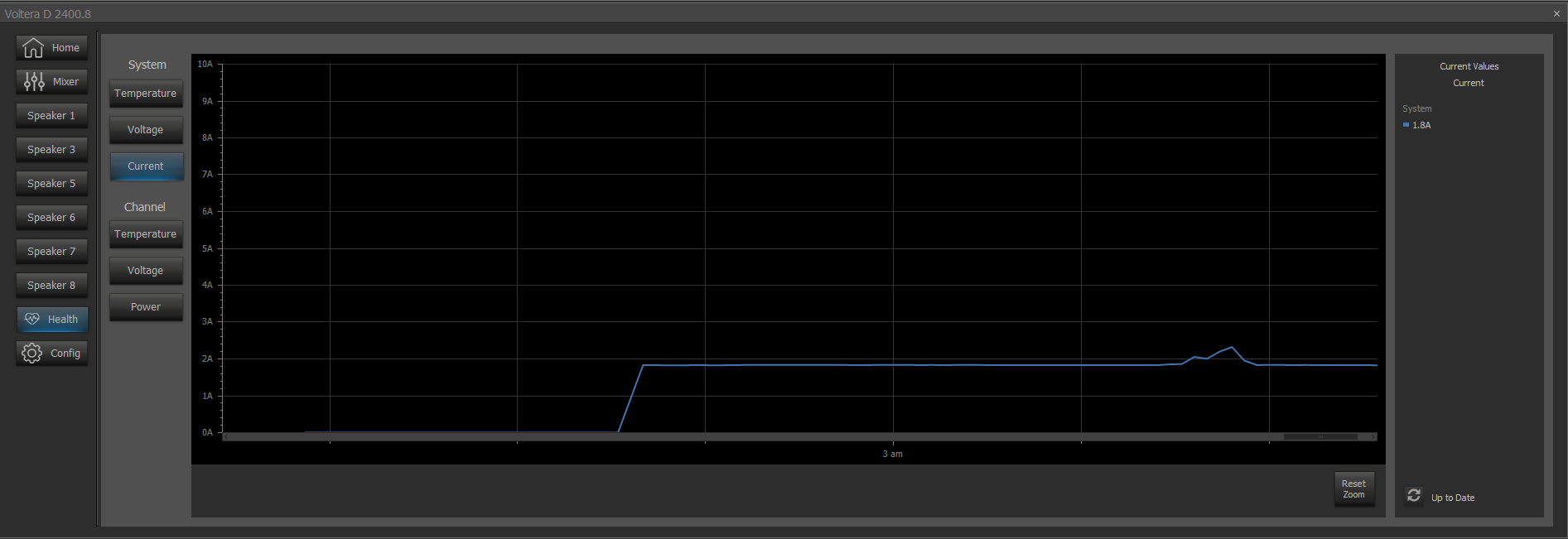
System Current is displayed in Amps.
Channel
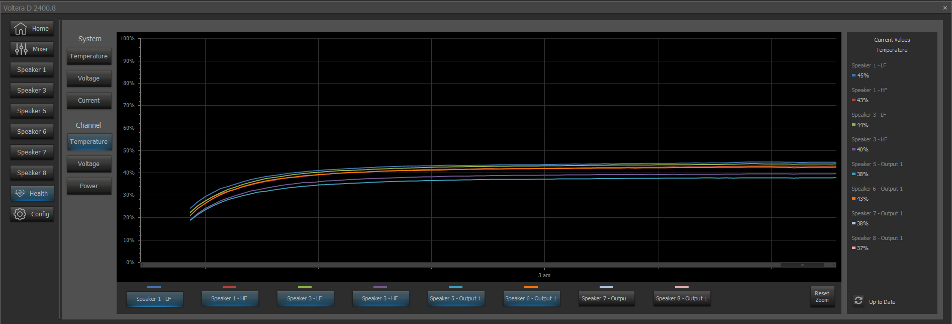
Each page in the Channel section has a toggle below the chart with a color indicator displayed above representing each configured speaker. Channel Temperature is displayed as a percentage. Temperature cannot exceed 100% and nearing this threshold should be understood as a problem with the device or its environment.
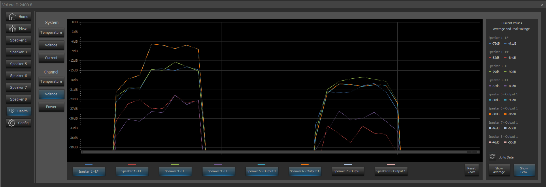
Channel Voltage is displayed in Volts. Use the buttons at the bottom of the Current Values section to alternate between displaying voltage average and voltage peak.
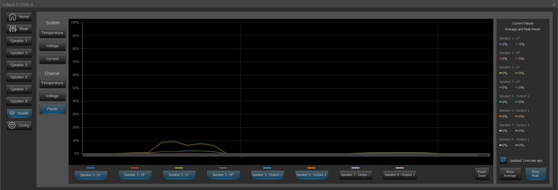
Channel Power is displayed as a percentage. Use the buttons at the bottom of the Current Values section to alternate between displaying power average and power peak.
Factory Reset
Factory Reset of a Voltera D(M) unit will load a default layout to the device with a system name of 'Voltera Default'.
To enable manual configuration of the device, the default configuration must be cleared by choosing 'Clear configuration' in Device Maintenance. The default layout can always be recovered by performing a factory reset on the device.
The default layout consists of a Dante Input block providing digital audio to all channels of a Voltera D(M) block. Dante channels follow the naming convention "DanteInput_ch", where 'ch' refers to the channel index. All channels of the Voltera D(M) block have been configured to pass audio with a flat response, allowing maximum amplification.
Tesira software will not Connect to System for a Voltera D running the default layout.
Sleep and Standby
A Voltera D(M) device may be set to Sleep or Wake from the Device Information menu under Device Maintenance. Sleep/Wake are only available while a device is configured. Unconfigured devices will only have Standby available. SSH (Secure Shell Console) is the only supported network protocol.
TTP commands to Sleep or Wake a device also apply to Standby while a device is unconfigured. While a device is Asleep the only available message is Wake. All TTP messages are available while a device is in Standby.
Proxying Expanders
Voltera D(M) units are able to allocate a small amount of general purpose DSP resource to blocks outside of the Voltera D block. This spare DSP resource can be used to proxy expander type devices. Technical support articles for Tesira Software can be found on Biamp’s Cornerstone knowledge-base support site. Click here: Tesira - Biamp Cornerstone
GPIO Logic
Voltera D(M) provides two logic I/O connectors, refer to Voltera D & DM Series Installation & Setup Guide. Click here: Biamp - Downloads
