Parlé Microphones
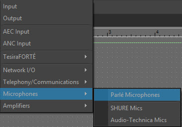
Microphone configurations for the Parlé TCM-1, TCM-1A, TCM-X, TCM-XA and TTM-X are available from the Object Toolbar via the I/O Block > Microphones menu item:
Initialization Dialog
When the Parlé Microphone object type is selected from the Audio Object Toolbar, the Parlé Mic Initialization dialog window is displayed:
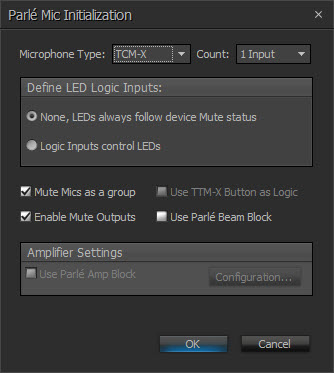
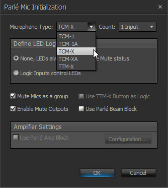
In the Parlé Mic Initialization dialog window, select the desired microphone type from the drop-down. Amplifier Settings will be disabled if the TCM-1, TCM-X or TTM-X are selected:
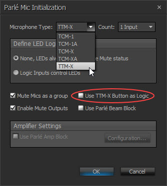
Use TTM-X Button as Logic is enabled when TTM-X is selected from the drop down in the Initialization dialog window:
NOTE: If more than one microphone input is selected for the TCM-1 and TCM-1A, the TCM-1EX expansion microphone must be used for microphones 2 and 3. If more than one microphone input is selected for the TCM-X or TCM-XA, the TCM-XEX expansion microphone must be used for microphone 2. If more than one microphone input is selected for the TTM-X, the TTM-XEX expansion microphone must be used for microphone 2.See Parle Microphone/Amplifier Wiring Diagrams for more information on TCM-1, TCM-1A, TCM-X, TCM-XA and TTM-X topology.
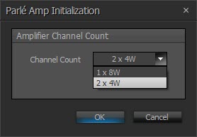
Parlé TCM-1A/TCM-XA Amp Initialization dialog:
|
Microphone Type |
Max Number of Inputs |
| TCM-1 |
3 |
| TCM-1A | 3 |
| TCM-X | 2 |
| TCM-XA | 2 |
| TTM-X | 2 |
|
Name |
Description |
|
Microphone Count |
Specifies how many microphones are to be supported. |
|
Define LED logic inputs |
Allows LED behavior to be customized:
|
|
Mute Mics as a group |
Specifies whether all microphones will be muted at the same time when the mute state of a single microphone is changed. |
|
Enable Logic Outputs |
Specifies if the Logic Output ports for mute state signalling are available on the Parlé Mic block. |
|
Use TTM-X Button as Logic |
Touch buttons will act as logic input (enabled for TTM-X devices only). NOTE: Option will stop the button from changing the mute state of the microphone. |
|
Use Parlé Beam Block |
Specifies if the individual beam outputs are available for use in the layout. |
|
Amplifier Setting |
Specifies if Parlé Amp block is to be created. |
|
Configuration |
Opens Parlé TCM-1A/TCM-XA Amp Initialization Dialog. Allows the selection of amplifier channel count. |
DSP Block Representation
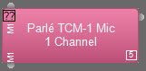
Parlé TCM-1 Mic Block with 1 Channel:
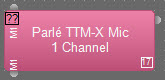
Parlé TTM-X Mic Block with 1 Channel:
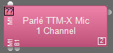
Parle TTM-X with Button Logic Enabled with 1 Channel:
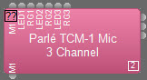
Parlé TCM-1 Mic Block with 3 Channels and LED Logic Input Nodes:
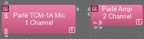
Parlé TCM-1A Mic and Amp Blocks:
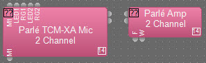
Parlé TCM-XA Mic and Amp Blocks with 2 Channels and LED Logic Input Nodes:
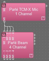
Parlé TCM-X Mic Block with 1 channel and Beam Block with 4 channels:
NOTE: TCM-X, TCM-XA and TTM-X only.
See this link for logic chart.
Control Dialog
See Parlé Software Terms and Definitions for more information.
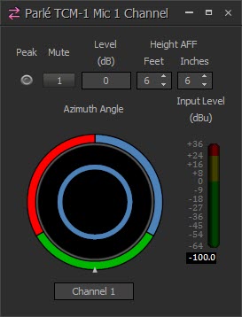
Parlé TCM-1/TCM-1A Control Dialog with 1 Channel:
NOTE: Microphone control dialog for the TCM-1 and TCM-1A is identical.
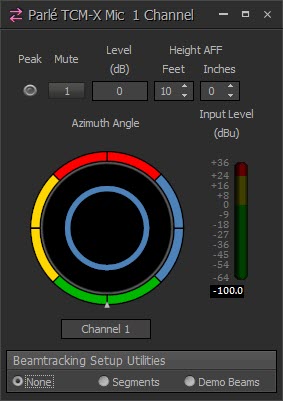
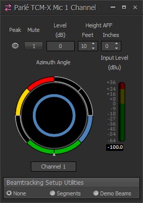
Parlé TCM-X/TCM-XA Control Dialog with 1 Channel:
NOTE: Microphone control dialog for the TCM-X and TCM-XA is identical.
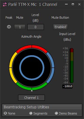
Parlé TTM-X Control Dialog with 1 Channel:
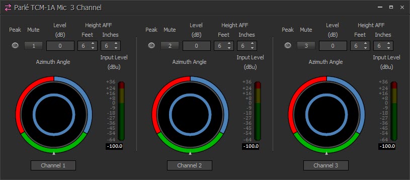
TCM-1/TCM-1A Control Dialog with 3 Channels:
TCM-X/TCM-XA Control Dialog with 2 Channels:
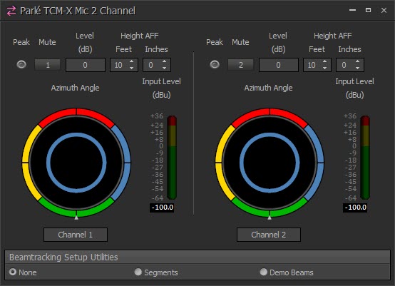
Disabling Beam Segments
Each beam can be enabled or disabled in 45-degree increments by clicking on the corresponding color-coded arc segment around the edge of the azimuth indicator. This allows for coverage only where it is needed.
TCM-X/TCM-XA Control Dialog with Segments and Arcs selected and unselected (TCM-X, TCM-XA and TTM-X only):
| Name | Description |
Range |
| Peak | Indicates a peak condition on the microphone channel. | On/Off |
| Mute | Mutes a single channel or all channels depending on the Initialization Dialog selection. | On/Off |
| Mute Button | Disables the mute button located on the microphone (TTM-X only). | Enabled/Disabled |
| Level (dB) | Sets the decibel level for each channel. | -100 to 0 dB |
| Height | Distance between the microphone and the floor. | TCM-1/TCM-1A = 4'-18' (Default of 6' 6") TCM-X/TCM-XA = 7'-18' (Default of 10') |
| Azimuth Angle | Displays the general location of where the microphone beam is directed. Each color represents a different zone. | 120° lobe per beam (TCM-1/TCM-1A) 90° lobe per beam (TCM-X/TCM-XA/TTM-X) |
|
Tracking Limits |
Disables tracking to specified sections on the microphone. |
|
| Input Level (dBu) | Indicates the input level of each channel. | -100 to 36 dB |
Beamtracking Setup Utilities temporarily override LED logic behavior to allow representation of Beamtracking features on the physical microphone. This feature is only available when connected to an active Tesira system.
|
Beamtracking Setup Utilities |
Description |
|
None |
LED ring follows Mute status or the state of the LED logic input node. |
| Segments |
Individual LEDs in the ring will be turned on or off to represent the state of the beam segments. |
| Demo Beams |
Individual LEDs in the ring will illuminate to show the current position of each beam as it is activated. Beams are illuminated either red or green. |
Note: While a Beamtracking Setup Utilities mode is selected, (e.g. Segments or Demo Beams), the device LEDs will always follow the device Mute state. This indication overrides the "Logic Inputs control LEDs' setting that may have been enabled for the block. Segments and Demo Beams are only used for setup, therefore they will time out after one hour.
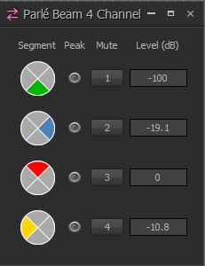
Parlé Beam Control Dialog
The Beam Control Dialog is configured to show channel, mute indicators and beam controls for each segment (TCM-X, TCM-XA and TTM-X only):
| Name |
Description |
Range |
|
Segment |
Reflects tracking limits specified in the Parlé Microphone control. | |
|
Peak |
Indicates a peak condition on the microphone channel. | On/Off |
| Mute | Turns the channel output signal on/off. | On/Off |
|
Level |
Adjusts the relative output volume. | -100 - 0 |
Parlé Amplifier Control Dialog
The amplifier dialog is configured to show channel and device indicators and controls for each enabled audio channel:
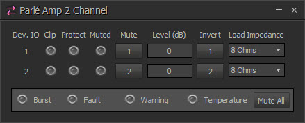
Channel Indicators and Controls
| Name | Description |
Range |
| Dev. IO | Indicates which amplified output(s) are controlled with this channel of the block. | 1-2 |
| Clip |
|
|
| Protect |
|
|
| Muted | Indicates the current state of the amplifier channel:
|
|
| Mute | Turns the channel output signal on/off | |
| Level | Adjusts the relative output volume. | -100 to 0 dB |
| Invert | Adjusts the polarity of the output signal. | On/Off |
| Load Impedance | Sets the load impedance being driven by the speaker output. | 4, 8 Ohms |
Device Indicators and Controls
| Name | Description |
| Burst | Indicates a burst condition is present.
|
| Fault | Indicates when a frame fault is active.
|
| Warning | Indicates when a frame warning is active.
|
| Temperature | Indicates a frame level thermal fault.
|
| Mute All | Mutes all channel on the Chassis. |
*If both the Fault and Temperature indicators are red, the amplifier will shutdown until power cycle. This could be an indication of a major error in the installation.
Parlé Processing Block
The Parlé Processing block allows for easier configuration of a system to work with Parlé microphones. See Processing Block for more information on accessing processing blocks for configuring a system with Parlé microphones. See this link for logic chart.