Parlé Microphone Best Practices
When configuring a system that utilizes Parlé microphones, certain practices should be taken to maximize system performance. The Parlé Processing Block offers optimal Beamtracking settings with minimal configuration. Additionally, this topic covers best practices when designing systems containing Parlé microphones outside the provided Parlé Processing Block. Go to Parlé Microphones and Parlé Processing Block for more information. See this link for the logic chart.
The Tesira Processing Library has pre-installed custom blocks. These custom blocks are recommended instead of the Parle Processing block when AI Noise Reduction is used. Details are available in the Cornerstone article Noise Reduction and Dereverberation.
Parlé Software Terms and Definitions
Beamforming microphones are arrays of microphone elements with "beams" (polar patterns) that can be controlled and shaped via DSP, allowing the beams to be "aimed" at specific areas of the room.
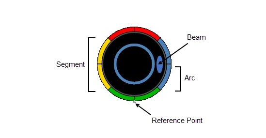
Beam: A polar pattern that refers to the sensitivity of any given microphone to the sounds coming to its central axis from different angles. The location of the beam within a segment can move between the segment limits. The center of a beam will never pass its boundary start/end.
NOTE: The width of the graphic representation is the not the same as the actual beam’s width. The center of the beam represents the current location of the beam’s tracker. The edges may appear to overlap the boundary start or end, but the center should not.
Segment: The space between the boundary start and the boundary end, the segment is the "wedge" that a beam moves within when beam tracking.
Beam Tracking: The movement of a beam within a defined segment to follow the talker.
Arc: A subsection of a segment. A segment is comprised of one or more arcs that can be used to expand/contract the tracking zone that a beam can move within.
Reference Point: Aligns to the Biamp logo on the physical device.
Boundary Start: The left boundary of a segment that a beam moves within. The center of a beam will never pass its boundary start/end.
Boundary End: The right boundary of a segment that a beam moves within. The center of a beam will never pass its boundary start/end.
Layout with Processing Blocks
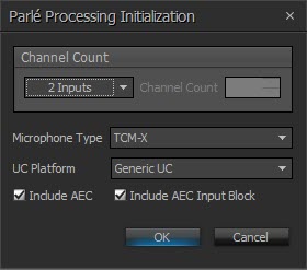
The images below show settings and a layout example with four microphone inputs, the Parlé Processing Block and the AEC Ref Block. Parlé Processing Blocks feature 1-12 microphone inputs. Logic Outputs are available for indication of the active microphones as well as if AGC is active. To place the AEC Ref Block, select "Include AEC" as shown in the initialization dialog below.
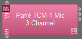
Parlé Processing Block with two TCM-1 Blocks:

NOTE: Custom must be selected to allow the user to expand the Parlé Processing block by clicking on the yellow '+' symbol in the top right-corner:


The individual DSP objects that comprise the block may be viewed by expanding the Processing Block using the yellow ‘+’ symbol in the top left-corner. The settings within the sub-blocks may be edited when the Room Acoustic Setting is "Custom". An example of an expanded Parlé Processing Block is shown below:

When expanded, the sub-blocks within the Parlé Processing Block can be controlled with their own control dialogs.

System Design Without Parlé Processing Block
Using the Parlé Processing Block is highly recommended, however in some situations the Parlé Processing Block may not be practical. For optimal performance, the following settings should be used:
DSP Blocks and Settings
DSP blocks should be placed on the layout in the following order:
- Parlé Mic
- AEC
- Gating Auto Mixer
- AGC
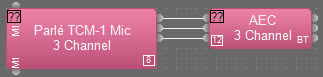
First, place the Parlé Mic block on to the layout with the desired number of inputs:
AEC Settings
After placing a Parlé Mic Input with the desired channel count, an AEC Input Block should be placed as the next item in the signal path. Select "Preconfigure for Beamtracking Mics". The Parlé Processing Block preconfigures AEC for Beamtracking, if not using the Parlé Processing Block, ensure AEC is configured for Beamtracking:

AGC in AEC will be automatically bypassed as described previously.
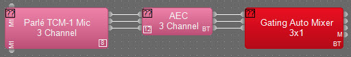
Use of the Gating Auto Mixer
Place a Gating Auto Mixer Block in the design as the next processing object in the signal path. Select "Preconfigure for Beamtracking Mics" to optimize the tracking performance.

Optionally, the check box to Enable Direct Outputs can be selected for logic tracking of the active microphone. Refer to the Logic Charts section for more information.
Placement of AGC
AGC blocks should be placed after the Gating Auto Mixer when using Parlé microphones. Placing these blocks ahead of the Gating Auto Mixer may result in unwanted sound ramping and biasing of the microphones.

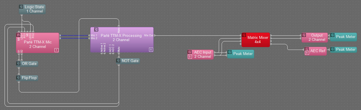
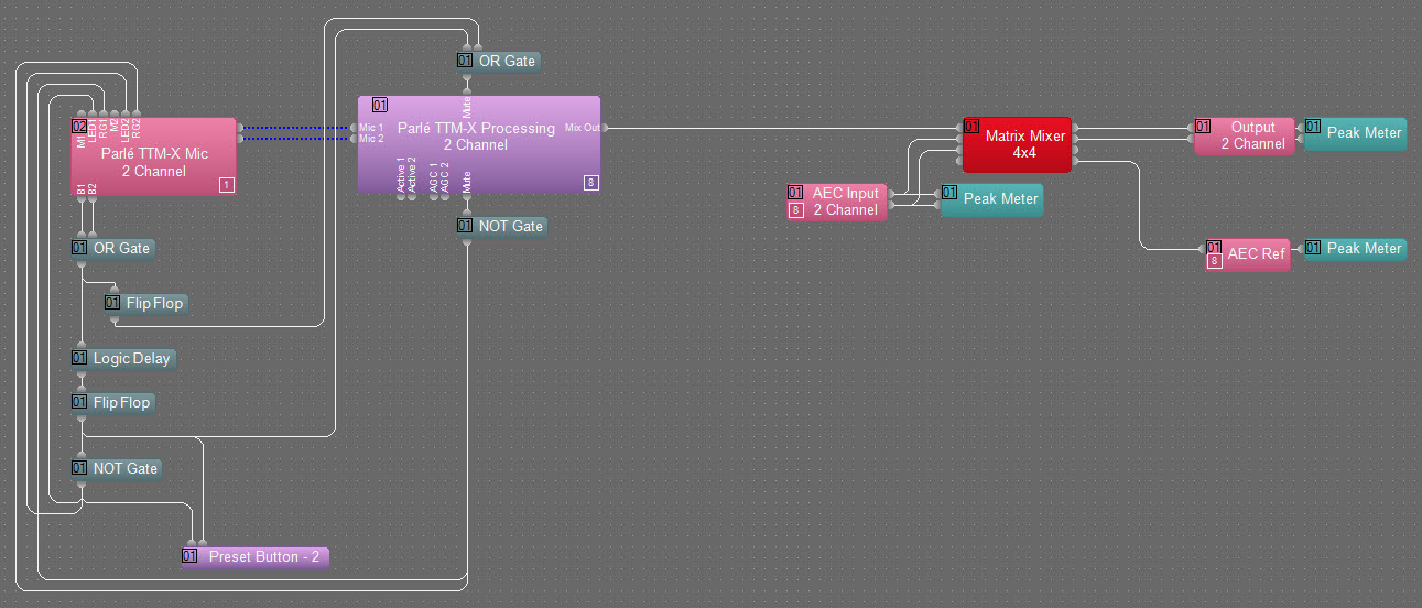
Use of the Mute Buttons on TTM-X
This example uses the momentary button press logic node from the TTM-X microphone to drive a flip flop that mutes the TTM-X microphone in the Parlé Processing Block (post AEC and Automixer). The Logic State here is used to turn the microphone LEDs on/off and can be controlled from an external control system and/or included in presets with system on/off presets.
-
The mute status output logic of the Parlé Processing Block drives the red/green status of the LEDs.
-
This must go through a NOT gate to invert the logic (logic high turns the LEDs green and logic low turns the LEDs red).
-
The included logic delay causes a second flip-flop to trigger events on a press-and-hold for 5 seconds.
-
Press-and-hold the microphone button for 5 seconds to turn off the LEDs and mute the block and then again to turn the LEDs on and unmute the Parlé Processing Block.
NOTE: A preset can be recalled for power on/off conditions and the button used to turn the system on and off.
This example uses the momentary button press logic node from the TTM-X microphone to drive a flip flop that mutes the TTM-X microphone in the Parlé Processing Block (post AEC and Automixer).
-
The mute status output logic of the Parlé Processing Block drives the red/green status of the LEDs.
-
This must go through a NOT gate to invert the logic (logic high turns the LEDs green and logic low turns the LEDs red).
-
A Logic State is required to enable/disable the LEDs.
NOTE: The Logic State here is used to turn the microphone LEDs on or off. It can be controlled from an external control system and/or included in presets with system power on/off presets.