Tesira Amplifiers - Rack Mount
The Tesira Amplifier class devices are designed for use with Tesira SERVER, SERVER-IO and TesiraFORTÉ AVB devices. Click here to jump to common features, etc. of the following legacy amplifiers:
AMP-4175R AMP-4350R AMP-4300R CV AMP-8175R
TesiraXEL 1200 Amplifiers
There are two models of the TesiraXEL 1200 amplifier: the 1200.1 and 1200.2. Each amplifier is rack-mountable and requires 2RU of rack space. Features and benefits of the amplifiers are detailed below. The TesiraXEL 1200 Amplifiers are also designed for use with Tesira SERVER, SERVER-IO and TesiraFORTÉ AVB devices, but are different in design and features from legacy Tesira rack-mount amplifiers.
Common Features
Both TesiraXEL 1200 amplifiers are AVB/TSN enabled, digitally-networked and feature four output channels. Each amplifier leverages unique power distribution architecture which allows users to distribute power to any output channel. The amplifier is capable of several different network topologies, to include single-cable, redundancy, daisy-chain, or separate control and AVB. The amplifiers feature four output channels and can receive control data and digital audio over AVB via one or two RJ-45 connectors on the back panel.
Both amplifiers support selectable impedance (4Ω, 8Ω, 70V, or 100V), are capable of supporting 802.1X authentication for added security and feature an audible locate function.
The front panel display features system and per-channel status LEDs, per-channel and mute all, locate and sleep functions. The front panel may be locked from software to prevent unauthorized changes.
NOTE: TesiraXEL 1200 amplifiers do not have an OLED display with menu navigation.
Benefits
- Functions as an integrated part of a Tesira networked media system.
- Full asymmetric loading allows power to be distributed per-channel as needs dictate.
- Selectable impedance (both Hi-Z and Lo-Z) per channel.
- Software-configurable media interface allows designers to choose their network topology (daisy chain, separate control and AVB or redundant AVB).
- Supports Single Network Connection Topologies.
- Can audibly locate connected speakers from the front panel to validate speaker runs without requiring the amplifier to be configured.
- Rapid Spanning Tree Protocol (RSTP) Support
Models
- TesiraXEL 1200.1 (1200W, single asymmetric bank)
- TesiraXEL 1200.2 (2 x 1200W for 2400W total, dual asymmetric banks)
The 1200.1 and 1200.2 are identical in functionality. The primary feature that will impact a user's design decisions is the total power available from each amplifier, as referenced above.
Asymmetric Power Distribution
Both TesiraXEL 1200 amplifiers feature the ability to redistribute unused power as needed to any channel desired, as long as the power doesn't exceed the overall maximum rating of the amplifier. Power values are set via a control dialog in Tesira software but may not be changed while the amplifier is connected to a system.
The TesiraXEL 1200.1 allows for a maximum power distribution of 1200W to any one channel (the remaining three channels would have no available power.)
The TesiraXEL 1200.2 allows for a maximum power distribution of 1200W to two channels (combination of channels 1/2 or 3/4 - the remaining two channels would have no available power. See Power_Bank for more information on how power is distributed between channels)
Any unused power will be intuitively displayed in the control dialog in the Tesira software. See TesiraXEL 1200 Amplifiers in the Components Object section for more information.
Power States
The TesiraXEL 1200 amps have two power states:
- Operating
- Sleep
In operating state, all components are powered.
Sleep Mode
Sleep mode is enabled or disabled via a logic input or by pressing the Sleep button on the front panel. When the amplifier is in sleep mode, the network processor is suspended and will not respond to network traffic. Daisy-chain pass-through will also be unavailable in sleep mode. The amplifier will not be discoverable while in sleep mode, yet other devices in a system are informed the device is entering sleep mode so as to avoid a 'missing device' fault.
Unconfigured devices will not enter sleep mode as they would not be discoverable.
In sleep mode, the +5V output on the logic connected will not provide voltage, therefore the amplifier cannot be brought up to operating mode (out of sleep mode) on its own. Yet the amplifier's sleep state may be controlled externally if the output on an external controller is connected directly to the sleep input pin.
The below diagram shows the default state of the GPIO:
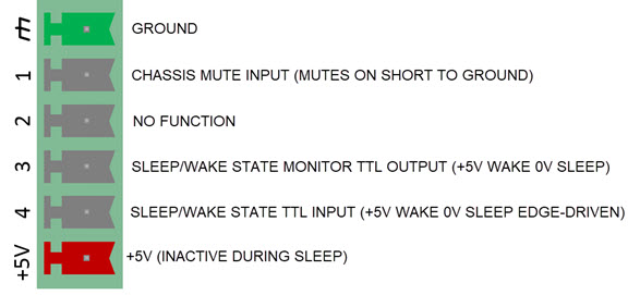
Rear Panel Logic I/O (GPIO)
The TesiraXEL 1200 amps support four channels of logic I/O on the rear panel and may be used in two mutually exclusive modes:
1) General purpose voltage control/logic I/O
-
- When used as a general purpose voltage control/logic I/O, each channel can be independently configured for use as a voltage control input, logic input or logic output (powered or un-powered).
2) Dedicated logic I/O for controlling the amplifier sleep and chassis mute functionality
-
- When used for dedicated logic I/O for controlling amplifier sleep and chassis mute, the logic I/O pins have specific function assignments that cannot be changed by the user. The dedicated logic I/O will function as the follows:
- One logic input brings the amplifier into or out of the low-power sleep mode.
- One logic input mutes all outgoing audio from the amplifier. This mute overrides all other mute settings and cannot be changed from software or the amplifier front panel.
- One logic output indicates whether the amplifier is in low-power sleep mode or normal operating mode.
- When used for dedicated logic I/O for controlling amplifier sleep and chassis mute, the logic I/O pins have specific function assignments that cannot be changed by the user. The dedicated logic I/O will function as the follows:
NOTE: TesiraXEL 1200.1 and 1200.2 front and back panel identical except for branding/naming.
Front Panel
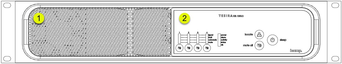
1. Ventilation Fan Cover
- Perforated cover that allows cool air into the chassis. Two variable speed, temperature-controlled fans allows air to circulate through the unit from front to the back.
2. Front Control Panel
- Displays information about the amplifier status as well as mute, locate and sleep functions.
Back Panel
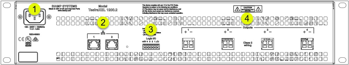
1. A/C Power Connection
- Allows for connecting an appropriate power cord.
- Each amplifier uses a switch mode power supply that has an operating voltage of 100-240V at 50/60 Hz.
2. Combined AVB/Control Ports
- Two gigabit RJ-45 ports allow connections for numerous network topologies.
3. Logic I/O
- Standard 6-pin logic IO may be used as a general purpose logic IO as well as allowing the amplifier to enter or exit sleep mode.
- See Rear Panel Logic I/O for more information.
4. Amplifier Output Connections
- Four powered speaker connections allow for audio output.
Front Panel Detail
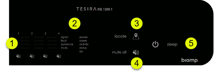
The TesiraXEL 1200 amplifiers are an endpoint-class device, therefore there is no OLED display or control buttons. Per-channel buttons allow mute functionality to be initiated from the device, and holding any mute button for two seconds will activate/deactivate a chassis-wide mute function.
1. Per-channel mute buttons
- Each audio output channel may muted individually. A red LED will indicate when a channel is muted.
2. LED Status Indicators
- Per-channel and overall system status is indicated by multi-colored LEDs on the front panel. See LED Indicators section, below.
3. Locate
- Pressing the locate button will play an audible signal that cycles through each connected output. Device status LEDs will flash green when locate is initiated.
4. Mute All
- Pressing the Mute All button will mute or un-mute all audio on the amplifier. If individual channels are already muted, pushing Mute All will mute all channels. Pressing Mute All again will un-mute all channels.
5. Sleep
- The amplifier has two power states that may be enabled or disabled from the front panel: Operating and Sleep. In sleep mode the amplifier will not be discoverable nor will it respond to network traffic. Unconfigured devices will not enter sleep mode.
LED Indicators
Front Panel LED indicators
| LED | Off | Green | Yellow | Red |
| Power | Unit not Powered | Unit is powered | Unit is in sleep mode | Not applicable |
| Alarm | No device fault active | Not applicable | Minor device fault active | Major device fault active |
| Activity | Not applicable | The device is an active part of an active system | Not applicable | Device is an inactive part of a system (Audio is stopped) |
| Status | Not applicable | Device configured. Ready to participate in the system | Device unconfigured. Ready to receive configuration | Device not ready to receive its configuration |
| AIS (Alarm in System) | No fault is active in any device in the system | Not applicable | Minor fault is active in a device in the system | Major fault is active in a device in the system |
Per Channel LEDs
|
LED |
Off |
Green |
Yellow |
Red |
| Signal | Amp AVB Input Signal is not present. | Amp AVB Input Signal is present. | Amp Output Signal present and attenuating. | Amp Input Signal is present and clipping. |
| Fault | Device is in sleep mode or channel is operating normally. | N/A | Channel is attenuated for device protection. | Channel is muted for device protection. |
|
Automute |
Channel is not in Automute |
N/A |
Channel is in Automute |
N/A |
| Mute | Channel is not muted, or device is in sleep mode. | N/A | N/A | Channel mute is activated. |
In sleep mode, the power LED will glow steady amber - all other LEDs are off.
Tesira Amplifiers (Legacy) Common Features
Legacy Tesira® Amplifiers are AVB/TSN enabled, digital networked, multi-channel amplifiers. The Tesira Amplifiers function as an integrated part of a Tesira audio system that is configured through the Tesira configuration software. The amplifiers serve as a dedicated endpoint making installations easier to design, support and maintain.
The front panel OLED display allows for adjustments such as single-channel mute or all-channels mute and provides feedback on overall status and channel performance. All models feature impedance monitoring, as well as dual AVB/TSN connections for network redundancy. Optional rear panel input slot(s) can be used for analog failover or as an IO expander. See details of supported cards below.
Each Tesira amplifier is a two rack space, rack-mountable device, powered by 100-240VAC.
The amplifiers are best suited for training rooms, lecture halls, performing arts, houses of worship or other applications where sound distribution or reinforcement is needed.
Supported I/O Cards
The chassis is modular and supports the use of the following cards:
- EIC-4 - 4 channel Mic/ Line Input card
- EOC-4 - 4 channel Mic/ Line Output card
- EIOC-4 - 2 channel Mic/Line Inputs and 2 channel Mic/ Line Outputs per card
BENEFITS
- Functions as an integrated part of a Tesira networked media system
- Receives an audio signal from anywhere on the AVB/TSN network
- Optional expander slot can be used for analog failover or as an expander
- Optional analog failover allows signal flow even if there’s a loss of the AVB/TSN audio stream
FEATURES
|
|
Models
- Tesira AMP-4175R
- Tesira AMP-4300R CV
- Tesira AMP-4350R
- Tesira AMP-8175R
|
Functionality |
4175R | 4300R CV | 4350R | 8175R |
| Channels |
4 |
4 |
4 |
8 |
| Watts per channel |
175 |
300 |
350 |
175 |
| Constant Voltage |
NO |
YES |
NO |
NO |
| Optional Expansion Cards |
1 |
1 |
1 |
2 |
Rear Panel
Tesira AMP-8175R
Tesira AMP-4175R, Tesira AMP-4350R and Tesira AMP-4300R CV
LED Indicators
Front Panel LED indicators
| LED | Off | Green | Yellow | Red |
| Power | Unit not Powered | Unit is powered | Unit is in standby. | Not applicable |
| Alarm | No device fault active | Not applicable | Minor device fault active | Major device fault active |
| Activity | Not applicable | The device is an active part of an active system | Not applicable | Device is an inactive part of a system (Audio is stopped) |
| Status | Not applicable | Device configured. Ready to participate in the system | Device unconfigured. Ready to receive configuration | Device not ready to receive its configuration |
| AIS (Alarm in System) | No fault is active in any device in the system | Not applicable | Minor fault is active in a device in the system | Major fault is active in a device in the system |
Per Channel LEDs
|
LED |
Off |
Green |
Yellow |
Red |
|
Signal |
Amp AVB Input Signal is not present. |
Amp AVB Input Signal is present. |
Amp Output Signal present and attenuating. |
Amp input Signal is present and clipping. |
|
Fault |
Device is in standby or channel is operating normally. |
N/A |
Channel is attenuated for device protection. |
Channel is muted for device protection. |
|
Failover |
Device isn’t using failover, or this channel has no failover input source assigned. |
Signal is present on failover input. |
Signal is present and Failover Mode Active |
Signal is not present on failover input. |
|
Mute |
Channel is not muted, or device is in standby. |
N/A |
Chassis mute is activated, and channel mute is not. |
Channel mute is activated. |
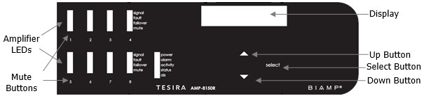
Front Panel Display
Amplifier Panel Overview
Amplifier Home Screen

Amplifier Menu Screen

Amp Settings Screen
From this screen the following functions are available:
- Set the amplifier power state to On or Standby.
- Chassis mute. Mute/Unmute all channels independent from each channel mute.
- Control the output level of each amplifier channel.

Channel > Level selection
- This will sync with the level attribute on the amplifier DSP block.