Telephone Interface
Initialization Dialog
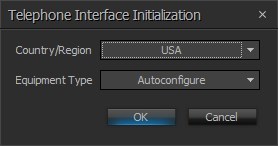
The Telephone Interface provides support and control for analog telephone lines. When the Telephone Interface is created from the Object Toolbar, an initialization dialog is produced. Select the Country the system will be installed in, to configure the telephone line and call signaling properties appropriately.
| Name | Description |
| Country/Region | A drop down menu to select the country in which the system will be operating, this configures the local call progress tones accordingly. |
| Equipment Type | Specifies what type of hardware the compiler should allocate the block to. Review the Equipment Type section for more details. |
DSP Block Representation
The Telephone Interface provides support and control for analog telephone lines. The Telephone Interface consists of three blocks,
- TI Receive
- TI Transmit
- TI Control/Status
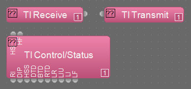
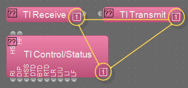
The component objects will have a number on the lower right, assigned by the software, which indicates which blocks are associated with each other, which is important when there are multiple Telephone Interfaces in the system. In addition, a dialer block or HD-1 can be associated with telephone or VoIP interfaces. The Dialer and HD-1 control are available in the Object Toolbar > Control section.
Information on logic is located here: TI_Control___Status.
Control Dialog
TI Receive
The TI Receive block is an input for received audio coming into the system via the telephone line.
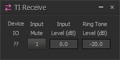
| Name | Description |
| Device IO | Indicates which physical hardware input is associated with that software channel. For Server and SERVER-IO devices is formatted as x.y - where x indicates which card slot and y indicates which channel on the card. |
| Input Mute | turns the signal off/on. |
| Input Level (dB) | controls the volume of the signal |
| Ring Tone Level (dB) | controls the volume of the generated ring tone when an incoming call is received. |
TI Transmit
The TI Transmit block is an output for sending audio out of the system via the telephone line.
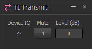
| Name | Description |
| Device IO | Indicates which physical hardware input is associated with that software channel. For Server and SERVER-IO devices is formatted as x.y - where x indicates which card slot and y indicates which channel on the card. |
| Mute | turns the signal off/on. |
| Level (dB) | controls the volume of the signal |
TI Control Status
TI Control/Status provides global line settings and status.
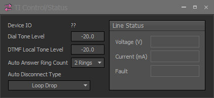
| Device IO | Indicates which physical hardware input is associated with that software channel. For Server and SERVER-IO devices is formatted as x.y - where x indicates which card slot and y indicates which channel on the card. |
| Dial Tone Level | sets the incoming dial tone level |
| DTMF Local Tone Level | sets the local volume of any generated DTMF tones. |
| Auto Answer Ring Count | sets the number of rings of an incoming call before the Telephone Interface will automatically answer the call, if Auto Answer is enabled on that line. |
| Auto Disconnect Type | sets what type of call termination signal the Telephone Interface will use to automatically disconnect the line when the call is finished. None, Loop Drop, Call Progress and Loop Drop + Call Progress can be selected. |
| Line Status | provides real-time information about the line Voltage (V) and Current (mA). If either of these values is outside of the normal expected range, a Fault message will be displayed. |
| Note |
| Line Status values on different phone systems may have different readings, but expected Line values will be in the region of 7.5V 32mA Off Hook. 54V, 0mA when On Hook. |
TI Control Status Logic
The TI Control/Status block has a number of logic nodes that provide additional functionality. See the Logic Charts Section for more details
- HS (Hook Switch) will take the line off hook on a rising edge and go on hook on a falling edge.
- HF (Hook Flash) will initiate a hook flash on a rising edge. The amount of time the line is momentarily disconnected is controlled by the Hook Flash Duration (ms) setting in the DSP Properties tab in the Properties window of the TI Control/Status block.
- RI (Ring Indicator) is a logic output that is normally low, and goes high when the corresponding line is ringing, and through the entire duration of ringing. When ringing has stopped, RI will go back to a low state.
- DIP (Dial In Progress) is normally low, and goes high during any dial operation.
- HSS (Hook Switch State) will be low when the Telephone Interface is on hook and high when off hook.
- DTD (Dial Tone Detect) is normally low and will go high when a dial tone is detected on the line.
- BTD (Busy Tone Detect) is normally low and will go high if a busy signal is detected on the line.
- RTD (Ring Tone Detect) is normally low and will go high if the far end of the outgoing call is ringing. This should not be confused with the RI (Ring Indicator) node, which indicates when a ring is incoming.
- LR (Line Ready) will output a high state when a valid telephone line is connected (line voltage and current within expected parameters).
- LIU (Line In Use) will output a high state when the phone is off hook or ringing.
- LI (Line Intrusion) will output a high state if another extension on the active line goes off hook. This is determined by sampling the line current when the Telephone Interface initially goes off hook. If the current rises by an amount consistent with another phone off hook on the line, this logic node will go high.
- LF (Line Fault) is normally low and will go high when a fault condition is detected (line voltage or current outside expected ranges). This would correspond to a message in the Fault field of the Line Status indicators in the TI Control/Status block.
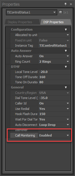
DSP Properties - Call Monitoring
In the TI Control/Status Properties window (DSP Properties) is a function labeled Call Monitoring. This setting should be enabled if a handset is connected in addition to a phone line, otherwise a fault condition will be triggered due to monitoring tolerances. The image below shows the location of the Call Monitoring function: