Audio-Technica Mic
When this object type is selected from the Object Toolbar, a Audio-Technica Mic Initialization dialog window is displayed. Please also review the Audio-Technica Mic Networking Considerations
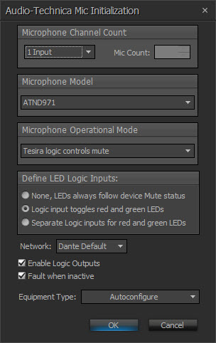
Initialization Dialog
| Name | Description |
| Microphone Channel Count | Determines the number of channels in the block. If Custom is selected from the drop-down list the number of channels can be specified between 1 and 64. |
| Microphone Model | Selects which Dante-enabled microphone will be supported by the block. The Audio-Technica ATND971, ATND8677 and ATND8734 are supported. |
| Microphone Operational Mode |
The operation of the mute button on the microphone base can be specified. Two push-to-toggle modes are supplied (initially muted and initially unmuted), as well as momentary push-to-talk and momentary push-to-mute. An External setting means that the mute button will display the current mute status by its color, but it will not change the mute state when pressed.
|
| Define Logic Inputs | Determines what type of logic inputs for controlling the LED behavior will be shown on the Dante Mic object, if any.
|
| Network | Allows the required Media Network Setup to be specified. |
| Enable Logic Outputs | Determines whether logic outputs will be provided on the bottom of the Dante Mic object. If enabled, one logic output per channel will be shown. If the Microphone Operational Mode is set to “External”, the logic output will correspond to the physical push button on the mic base. It will be a logic high when the button is pressed and logic low when not pressed. In all other Microphone Operational Modes, the logic output will follow the mute state of the microphone: high when muted and low when unmuted. |
| Fault when Inactive | If enabled, missing microphone channels or flows expected by this block will present a fault in the Tesira system. If disabled, microphone channels or flows expected by this block will not present a fault or log message in the Tesira system. |
| Equipment Type | Specifies what type of hardware the compiler should allocate the block to. Review the Equipment Type section for more details. |
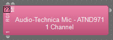
DSP Block Representation
More information on logic is located here: Audio-Technica_Mic
DSP Properties
| Name | Description | Range |
| Show Channel | Displays information and settings specific to the selected channel. | |
| Allocated Unit | Assigns the component (DSP block) to a particular unit in the system. | |
| Fixed in Unit | Prevents the compiler from assigning the unit elsewhere. | |
| Delay EQ Group | Aligns the timing synchronization for the blocks within the chosen group. See Delay Equalization for more details. | |
| Instance Tag | Allows a unique custom name to be used instead of the default Instance Tag. | |
| Network | Allows the required Media Network Setup to be specified. Network selection is not supported in TesiraFORTÉ Only Mode so will not be available. | |
| Device I/O |
Displays the physical Logic I/O channel(s) on the Tesira device this block has been assigned. |
|
| Gain | Sets the Microphone Preamp gain to either +30, +40, +50 dB. | +30, +40 or +50dB |
| Low Cut | When On (default), applies an 80Hz Low Cut filter to the microphone audio. | True or False |
| Muted | Turns the input signal on/off. Mutes or unmutes the signal. | On or Off |
| Level | Adjusts the relative input volume. | -100 to +12 |
| Level Min | Minimum on controllable range. | -100 |
| Level Max | Maximum on controllable range. | 12 |
| Inverted | Adjusts the polarity of the input signal. | True and False |
| Channel Name | Allows an individual Dante name of each channel. Can be changed in the property sheet as well as in the control dialog. | |
| Microphone Mode | Defines logic behavior of the microphone. | |
| Microphone Model | Allows selection of appropriate Audio-Technica model. | |
| Fault when Inactive |
If enabled, missing Dante channels or flows expected by this block will present a fault in the Tesira system. If disabled, Dante channels or flows expected by this block will not present a fault or log message in the Tesira system. |
True or False |
| LED Logic | Defines LED behavior. | |
| Enable Logic Outputs | Enables logic outputs for custom logic functions. | True and False |
Control Dialog
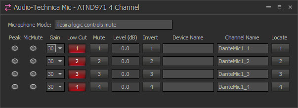
Above: ATND971 Control dialog (4 channel)
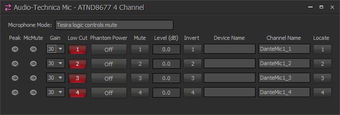
Above: ATND8677 Control dialog (4 channel)

Above: ATND8734 Control dialog (2 channel)
Channel Indicators and controls
| Name | Description | Range |
| Peak | A software indicator that flashes when the input signal is within 3dB of clipping. | |
| Mic Mute | Indicates that the microphone’s internal mute circuit has been activated. | |
| Gain | Sets the Microphone Preamp gain to either +30, +40, +50 dB. | +30, +40 or +50dB |
| Low Cut | When On (default), applies an 80Hz Low Cut filter to the microphone audio. | |
| Phantom Power | (ATND8677 Only) Enables 12V Phantom Power. | |
| Mute | Turns the input signal on/off. | On or Off |
| Level | Adjusts the relative input volume. | -100 to +12 |
| Invert | Adjusts the polarity of the input signal. | 0° or 180° |
| Device Name | The Hostname of the transmitting device. Is read only in the Tesira a Interface. Must be unique. Can be changed via Dante Controller software. | |
| Channel Name | Allows an individual Dante name of each channel. Can be changed offline in the property sheet. | |
| Locate | Allows the user to locate the physical microphone. When pressed, the LEDs on the microphone flash. |
Dante Channel Naming Conventions
Initially all channels will be given names in the form <Instance Tag>_<channel number>, where Instance Tag is the default value when the block is created and channel number is within the block, starting with 1.
All Dante names and labels are up to 31 characters in length. Name and label comparisons are case-insensitive; “Guitar” and “guitar” are treated as the same label. Unicode and non-roman characters are not supported.
Device names should follow Domain Name System (DNS) hostname rules. Legal characters are A-Z, a-z, 0-9, and '-' (dash or hyphen). Device names should follow Domain Name System (DNS) hostname rules. Legal characters are A-Z, a-z, 0-9, and '-' (dash or hyphen). Device names must begin with A-Z (or a-z).
Channel labels may use any character except '=' (equals), '.' (full stop or period), '@' (at), \, < and >. Channel labels must be unique on a device. Channel labels do not need to be unique on the network as they are always qualified by device (channel@device).
Please review the Dante Networking and the Audio-Technica Mic Networking Considerations section for more details