Split Pass Through Input
Split Pass-Through blocks allow associated input and output wiring nodes to be placed in separate locations, with an implicit or 'wireless' connection being maintained between them. Split Pass-Through blocks allow custom signal routing and labeling, but provide no actual signal processing.
Initialization Dialog
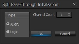
| Name | Description |
| Type | Selects whether the blocks are for Audio or Logic connections |
| Channel Count | Selects the quantity of input/output connections to be provided by the blocks |
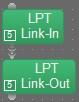
DSP Block Representation
Separate 'Link-In' and 'Link-Out' blocks are placed for input and output connections. APT stands for Audio Pass-Through. LPT stands for Logic Pass-Through.
Audio Pass-Through
Wiring nodes appear on the left side of Audio Pass-Through input blocks and on the right side of Audio Pass-Through output blocks.

Logic Pass-Through
Wiring nodes for Logic Pass-Through input blocks are on the top and Logic Pass-Through output blocks are on the bottom.
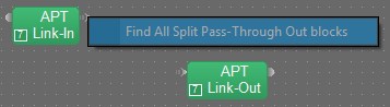
Link-In and Link-Out blocks are also numbered to identify their association. Their unique ID number appears in the bottom left corner of the block. More than one Link-Out block can be placed in association with an existing Link-In block (see Split Pass Through Output), and all associated blocks will have the same ID number. Right-clicking on the output arrow port will show a Find All Split Pass-Through Out Blocks option, this can be used to find and highlight all the associated Split Pass-Through Out blocks.
Note that Split Pass-Through blocks cannot be used to send audio from one partition to another. A Partition Connector Audio Transmitter is required for this purpose.
Control Dialog
There is no control dialog associated with Pass-Through objects as they provide no actual signal processing functions.