Split Pass Through Output
More than one Link-Out block can be placed in association with an existing Link-In block (see Split Pass-Through Input). Split Pass-Through blocks allow custom signal routing and labeling, but provide no actual signal processing.
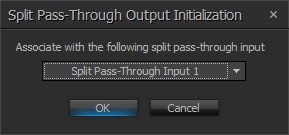
Initialization Dialog
The initialization dialog is used to select which existing Link-In block the new Link-Out block should be associated with. The new Link-Out block will include the appropriate number of output wiring nodes, and the same numbered association, as other Link-Out blocks already associated with the selected Link-In block. Additional Link-Out blocks allow a single set of input connections to be distributed to multiple sets of output connections.
DSP Block Representation
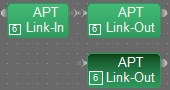
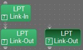
Separate 'Link-In' and 'Link-Out' blocks are placed for input and output connections. APT stands for Audio Pass-Through. LPT stands for Logic Pass-Through.
Audio Pass-Through Output
Wiring nodes appear on the right side of APT output blocks. The lower, darker shaded APT Link-Out object in the image below is the Split Pass-Through Output that was added.
Logic Pass-Through Output
Wiring nodes for Logic Pass-Through output blocks are on the bottom. The right-side, darker shaded LPT Link-Out object in the image below is the Split Pass-Through Output that was added.
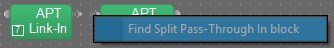
Link-Out blocks are also numbered to identify their association with their Link-In counterparts. Their unique ID number appears in the bottom left corner of the block. Multiple Link-Out block can be placed in association with an existing Link-In block, and all associated blocks will have the same ID number. Right-clicking on the input arrow port will show a Find Split Pass-Through In Block option, this can be used to find and highlight the associated Split Pass-Through In block.
Control Dialog
There is no control dialog associated with Pass-Through objects as they provide no actual signal processing functions.