Device Maintenance Settings
Device Information
Device Information provides information (such as firmware version, input/output configuration, etc.) regarding the selected device:

Note: Some Device Information Property Names and Values are device specific. For example, Sleep/Wake options are available for Voltera D but may not be available for other devices.
Date Time Settings
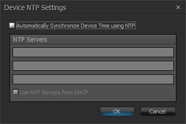
Date/Time Settings is used to configure time zone, daylight savings time adjustments and NTP (Network Time Protocol) servers. The date and time can be manually set or the unit can be synchronized to the clock of the host PC. The default NTP server is time.biamp.com.
NTP Settings provides a list of three NTP servers to which the device can automatically synchronize. If the network provides a DHCP server, it can also be chosen as the NTP server.
Network Settings
Network Settings allows for manipulation of a device’s network configuration. There is dedicated tabs for the Control, AVB Dante interfaces (on supported devices or devices with appropriate card(s) installed) and MAC Addresses. There is also a dedicated Port Usage tab for devices that support configuring usage of the device's network ports. Each will appear on a separate tab. If multiple digital audio cards are being used in a SERVER or SERVER IO, each will have their own dedicated tab and will provide reference to the physical card slot number in which they are installed.
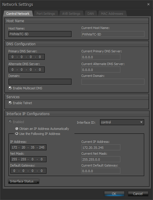
Control Network Settings Tab
The Network Settings dialog allows the following to be configured:
Host Name
- Host name - Alphanumeric and unique with no spaces
DNS Configuration
- a Primary and alternate DNS Server can be specified, as well as a domain and multicast DNS.
| NOTE |
|
Some network settings such as the Host Name will not be available unless the device is in an un-configured state. A Clear Configuration action is required of the device to make changes to the Host Name field. Trying to modify the Host Name via TTP will result in an error message if the system is currently configured. In the scenario where a system is configured and Clear Configuration is used to change the Host Name, the Equipment Table will need to be re-opened and updated to reflect the new details, and the configuration re-sent to the system. |
Services
-
Ability to enable or disable the Telnet port (port 23)
-
Ability to enable or disable the SSH port (port 22)
For further details on using these protocols for system control refer to the Third Party Control section.
-
Ability to enable or disable Rapid Spanning Tree Protocol (RSTP)
NOTE: Enabling RSTP will only be available when a TesiraCONNECT or TesiraXEL amplifier is selected. RSTP is enabled by default for a TesiraCONNECT device, but will not be available for the TesiraXEL unless daisy chain and RSTP are enabled from the Port Mode tab. RSTP will not be shown for any devices that do not support this functionality.
-
The HTTPS(+SSH) allows enabling or disabling a hosted webpage in Server Class devices that support this functionality.
NOTE: This parameter is disabled by default, enabling it to turn on the Events Scheduler interface. Enabling this service will also enable SSH, which is required for the Event Scheduler to function.
-
The IGMP allows TC-5D devices to participate in IGMP enabled networks to allow multicast Dante flows.
Interface IP Configurations
Settings related to automatic or manual IP addressing can be defined here.
The Interface ID drop down is used to select the Control or AVB Media Interface.
| Note |
|
By default the Control and AVB networks are separate. Combining control signalling to AVB expander devices is an advanced configuration. Please review the following sections before enabling Control Signalling on the AVB network. |

NOTE: Not all services are available across all devices.
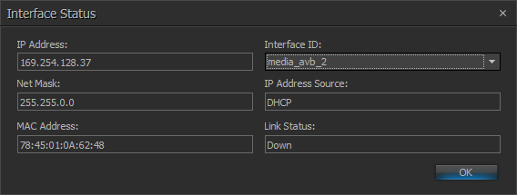
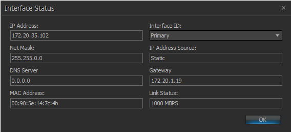
Interface Status
Interface Status shows the current connection details for the chosen interface.
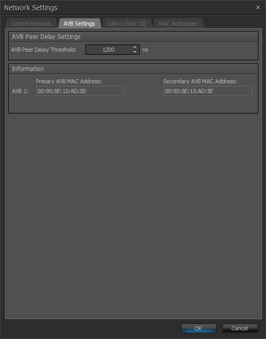
AVB Settings Tab
The AVB Settings tab allows user to adjust the AVB Peer Delay Threshold (1200ns by default). This adjustment may be required if media converters are used to connect to the expanders and there are audio dropouts happening. In this case a minimum value of 10,000ns should be used in this field. The expanders should also have the same value specified using the Remote Device Maintenance > Network Settings dialog.
NOTE: when a TesiraCONNECT device is selected, the Information window is unavailable.
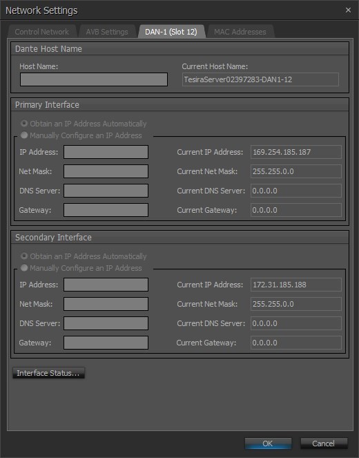
Dante Network Settings Tab
The hostname, DNS and IP configuration of the Dante interface can be set as needed.
| NOTE |
|
Some network settings such as the Host Name will not be available unless the device is in an un-configured state. A Clear Configuration action is required of the device to make changes to the Host Name field. Trying to modify the Host Name via TTP will result in an error message if the system is currently configured. In the scenario where a system is configured and Clear Configuration is used to change the Host Name, the Equipment Table will need to be re-opened and updated to reflect the new details, and the configuration re-sent to the system. |
Interface Status shows the current connection details for the chosen interface.
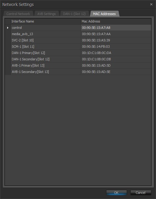
MAC Addresses Tab
MAC Address, Card type and Slot information can be viewed.
Port Settings Tab
The port settings tab is only available when a device is selected that supports configuring usage of the device's network ports.
This Port Settings screen allows the user to change port configurations for the TesiraFORTÉ X:

NOTE: The user must define port before sending configuration.
| Port Mode Settings | Description |
|
Dedicated Control, and Media |
Port 1 Control/VoIP, Ports 2-5 Media |
| Dedicated Control, VoIP, and Media | Port 1 Control, Port 2 VoIP, Ports 3-5 Media |
| Dedicated Control, VoIP, AVB, and Dante | Port 1 Control, Port 2 VoIP, Port 3 AVB, Port 4 Dante, Port 5 Disabled |
|
Converged Control, VoIP, and Media |
Ports 1-5 Control/VoIP/Media |
See System Network Considerations for more information on the above settings.
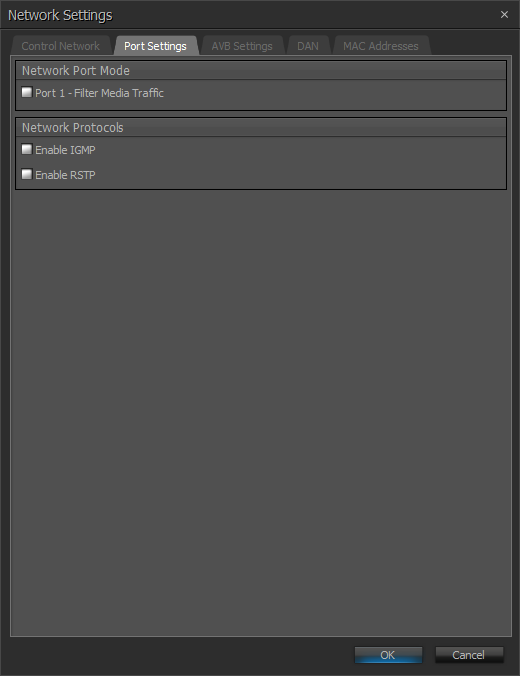
This Port Settings screen allows the user to change port configurations for the TesiraCONNECT TC-5/5D:
| Port Mode Settings | Description |
|
Port 1 - Filter Media Traffic |
The Port 1 - Filter Media Traffic checkbox suppresses both AVB (MSRP, MVRP, gPTP) and Dante (PTP) traffic out of port 1. When checked this forces port 1 to allow control port traffic only (no Dante or AVB traffic). This blocks Dante discovery across the port as well, requiring Dante Controller to be connected on the same network as ports 2-5. TC-5 is not a Dante endpoint but will pass Dante network traffic. |
|
IGMP |
IGMP is a delivery system that delivers single streams of information to multiple recipients. |
|
RSTP |
Enabled by default, RSTP ensures a loop-free topology for ethernet networks. |
See System Network Considerations for more information on the above settings.
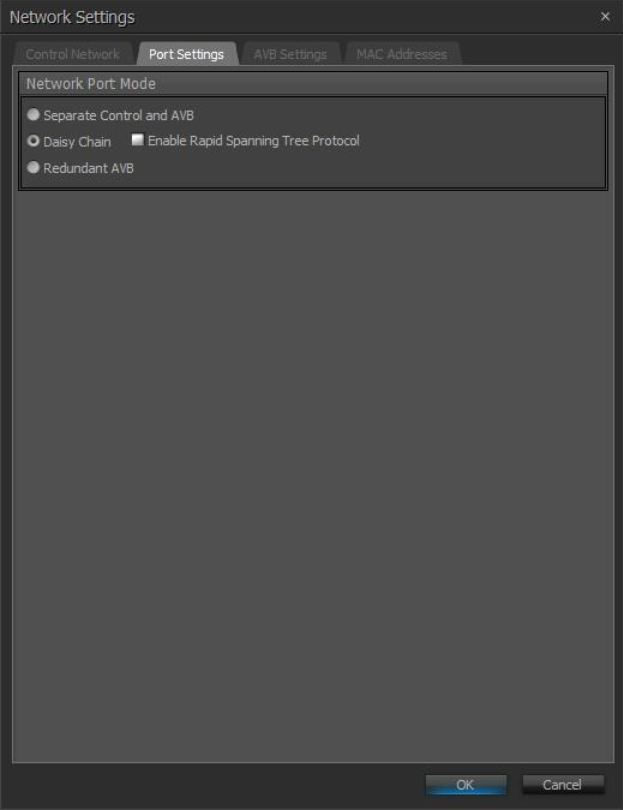
This Port Settings screen allows the user to change port configurations for the TesiraXEL 1200.1/1200.2 Amplifiers.
When Daisy Chain is selected, users will have the option of enabling Rapid Spanning Tree Protocol (RSTP). RSTP prevents network loops from impacting network performance. See TesiraXEL_1200_Amplifiers for more information:
| Port Mode Settings | Description |
|
Separate Control and AVB |
Allows for separating control and audio data. Control and AVB ports do not exchange information therefore they may be connected to different networks. |
|
Daisy Chain |
Allows the amplifier to provide network connectivity to multiple devices without the need for an additional Ethernet switch (default). Enabling RSTP prevents network loops from affecting performance. |
| AVB | Allows a single device to be connected to two different networks. |
See System Network Considerations for more information on the above settings.
This Port Settings screen allows the user to change port configurations for the Voltera D(M) Amplifiers:

| Port Mode Settings | Description |
|
Dedicated Control and Media |
Port 1 and Port 2 supports a control connection for device discovery, management, and programming. Port 2 also supports network media in this mode. |
|
Converged Control and Media |
Port 1 supports both control and network media in this mode. |
| Redundant Dante | Port 1 supports control and primary network media while Port 2 supports secondary network media in this mode. |
See System Network Considerations for more information on the above settings.
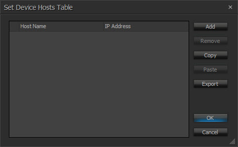
Hosts Table
The Hosts Table allows for hostname network mapping in the absence of a DNS server. The table simply maps an IP address to the hostname of another unit.
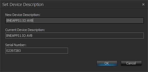
Device Description
Device Description allows the selected device to be given a descriptive name.
Port Setting
Port Setting selects the baud rate for the RS-232 ports on the selected Tesira server-class device. Serial ports can be configured to use with Command string blocks, TTP inputs, both, none or allow Control Tunneling. See the RS-232 section for more details.
A Tesira software reboot is required after a serial port usage type or baud rate change has been made.
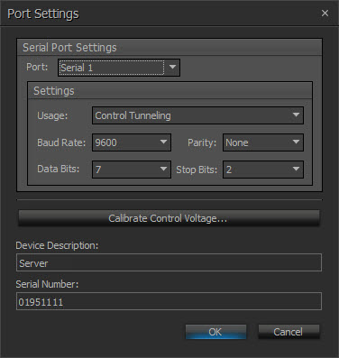
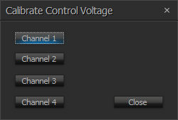
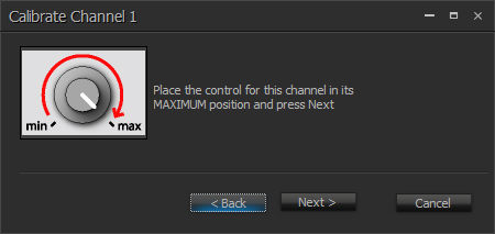
Calibrate Control Voltage is used to calibrate the GPIO connections on a Server SNC-1/SNC-2 card, TesiraFORTÉ or TesiraLUX device.
Security Settings
Security Settings allows security access and permissions to be implemented on a Tesira system. Please refer to the System Security page for information on protecting configured and unconfigured systems.
Manage Web Credentials
Manage Web Credentials allows resetting the username and password required to access web-based functions in Tesira. User is reset to admin. Password is reset to the device serial number. Click OK to confirm resetting the credentials:
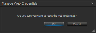
A dialog will inform the user if the reset was successful:
Configure 802.1X
Configure 802.1X allows the configuration of 802.1X data for devices to authenticate with an 802.1X-enabled network. The interfaces supported are Control, AVB and VoIP. This function is only enabled on server-class devices and the TesiraXEL 1200 amplifiers.
Select a device from the Device List to configure. If an unsupported device is selected, the user will be presented with the following dialog:
If the device supports 802.1X but is disconnected for any reason when the user selects "Configure 802.1X," or if the selected device cannot be communicated with (such as it is connected to the authenticated port but hasn't authenticated,) the following message is displayed:
| NOTE |
|
Make sure the device is connected to an un-authenticated port to configure 802.1X |
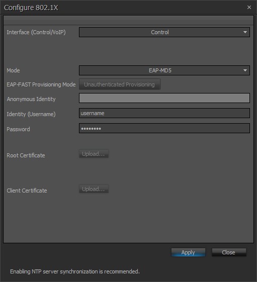
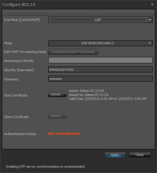
For supported devices, the user will be given the option to configure the Control port, VoIP or AVB. Enabling Network Time Protocol (NTP) server synchronization is recommended when configuring 802.1X. See Date_Time_Settings for more information. Initial dialog with Control selected in EAP-MD5 Mode shown below:
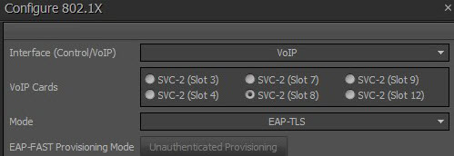
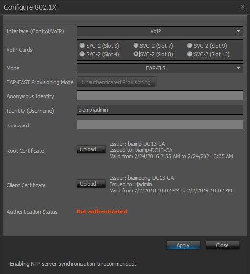
For VoIP, if multiple cards are present they will be shown below the Interface (Control/VoIP) dropdown:
| NOTES |
|
When switching between the Control, VoIP and AVB interfaces, all changes made will be retained and applied if "Apply" is clicked. All fields are the same for Control, VoIP and AVB settings, except as noted. Data is checked in real time while users enter data. Required data, errors and missing data will be highlighted with a tooltip. |
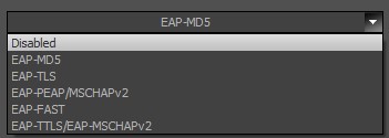
Mode - establishes the protocol by which the authentication takes place:
| Mode | Description |
| Disabled | Default setting |
| EAP-MD5 | Challenge-based password |
| EAP-TLS | Certificate-based two-way authentication |
| EAP-PEAP/MSCHAPv2 | Server authentication via certificate; client authentication via another EAP method |
| EAP-FAST | Certificate-based two-way authentication |
| EAP-TTLS/EAP-MSCHAPv2 | Optional server authentication via certificate; client authentication via another EAP method |
All Mode options shown below:
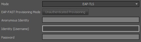
Depending on which Mode is selected, disabled fields will be shaded light grey. Required fields will be highlighted.
EAP-FAST Provisioning Mode - the user will have the option of selecting the following options:
- Unauthenticated Provisioning
- Authenticated Provisioning
Anonymous Identity - optional field. Only enabled when "EAP-FAST" or "EAP-TTLS/EAP-MSCHAPv2" is set as Mode. Identity (Username) - disabled if Mode is disabled. Credentials are required for all other Mode settings. Password - disabled if Mode is disabled or set to "EAP-TLS." Example of EAP-TLS required field Identity (Username) highlighted and disabled fields shaded in light grey:
Certificates
Root Certificate - gives users the option to upload their own root certificate. Uploading a root certificate option is disabled if Mode is set to one of the following:
-
- Disabled
- EAP-MD5
- EAP-FAST and EAP-FAST Provisioning Mode set to "Unauthorized Provisioning"
Click the "Upload" button to select a certificate from a file browser. The following information will be shown next to the Root Certificate Info text when a valid certificate is imported:
-
- Issuer
- Issued to
- Valid from
- Valid to
NOTE: Root Certificate formats must be either .pem or .der. and is limited to a size of 10K (10240 bytes).
Uploaded Root Certificate shown below:
Client Certificate - Click the "Upload" button to select a certificate from a file browser. The following information will be shown next to the Client Certificate Info text when a valid certificate is imported:
-
- Issuer
- Issued to
- Valid from - Valid to
- Only required in EAP-TLS mode.
For authentication methods that require this certificate, the Identity (Username) must match the text next to "Issued to:" in the fields to the right of Client Certificate preceded by the domain name. See image below for an example of the correct format: "biamp" being the domain, and "admin" being the username. Note that the domain and username are provided as examples only; in order for a device to authenticate on the server, a valid username must be entered that exists on the authentication server.
NOTE: Client Certificate format must be .pem. and is limited to a size of 10K (10240 bytes).
Uploaded Client Certificate shown below:
There are numerous potential issues to consider if a certificate fails to upload or validate:
- The file is empty
- The certificate file has exceeded the maximum size limit of 10K (10240 bytes)
- The uploaded Root certificate has failed validation; make sure the file has a certificate section and no private key
- The uploaded Client certificate has failed validation, make sure the file has a certificate section and does have a private key
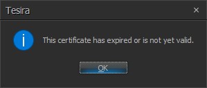
- The certificate is expired or not yet valid*
* Uploading a certificate that is expired or has a future valid-from date is allowed, but the user will receive the following warning message:
| NOTE |
| On some servers the Identity (Username) must be unique for each port on the switch. For example, two VoIP ports cannot use the same Username nor can a Control and VoIP port use the same Username. This applies to devices as well (two or more devices cannot use the same Username.) |
When all information is entered click "Apply." Users will be presented with a dialog box if there is any incomplete or missing information:
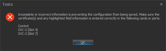
Settings will not be saved until the correct data is entered. Note that even if no changes are made to the Control Port interface configuration from the Configure 802.1X dialog, clicking "Apply" will force the authentication process to restart.
A status dialog will show the user that configuration changes have been applied and authentication is in progress:

Authentication Status - the following statuses may be displayed:
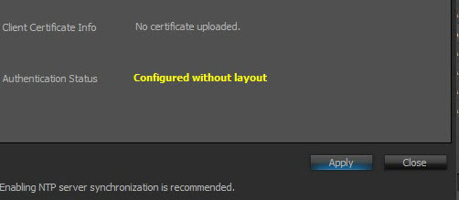
- Configured without layout - indicates 802.1X is configured on the VoIP card but there is no layout on the device (this status only applies to VoIP)
- Authenticating - 802.1X authentication in process with the server
- Authenticated - 802.1X authentication successful
- Not Authenticated - 802.1X authentication failed
See below for an example of the"Configured without layout" status:
| NOTE |
|
802.1X negotiation only occurs during a link change from a non-secure port to an 802.1X-enabled port on the Control interface. |
VoIP Authentication
Note that both the Control and VoIP ports will raise a fault if authentication fails, showing a fault message and illuminating the fault light on the front panel of the device. Yet when the VoIP card again attempts to authenticate, the fault light and message will clear (approximately every 30 seconds) and will remain off during the reboot/attempt to authenticate (approximately 10 seconds.)
This cycle will continue until the VoIP port successfully authenticates.
Clear Configuration
Clear Configuration clears all current system design data from the selected device(s) and resets the System ID to 0 (Zero). To associate a new configuration to the device a Clear Configuration is required before uploading the new configuration. For running systems, this happens automatically whenever there is a change to the running system file.
Update Firmware
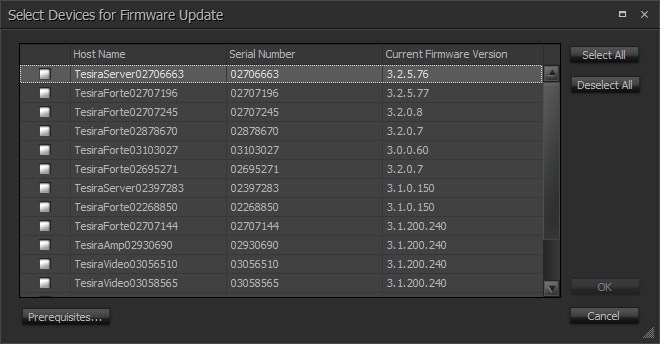
Update Firmware produces a file browser window where the firmware file (.tfa or .tfa2) can be selected.
When a valid firmware file is chosen, a dialog window is produced that shows all discovered devices in a table with columns indicating System ID, Device IP Address, and other details for each unit. To specify a unit for updating, place a check in that unit’s Update box. Buttons are provided to Select All entries and Clear All entries. Press the OK button to perform the firmware update on the selected units.
Clear Event Logs
Clear Event Logs will remove all log entries from the selected device. The Event Logs may be used to assist in troubleshooting a Tesira system. A prompt confirming the logs will be cleared will be displayed first.
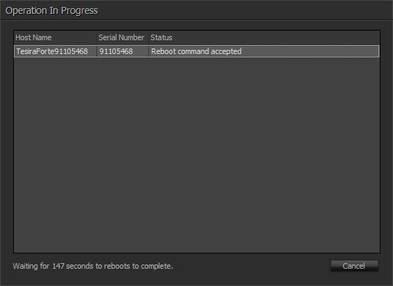
Reboot Device
Reboot Device will powercycle the selected device. A count down timer will begin allowing sufficient time for the device to return to normal operation. Once the timer reaches 0 seconds, Device Maintenance will close and reopen a new device discovery.
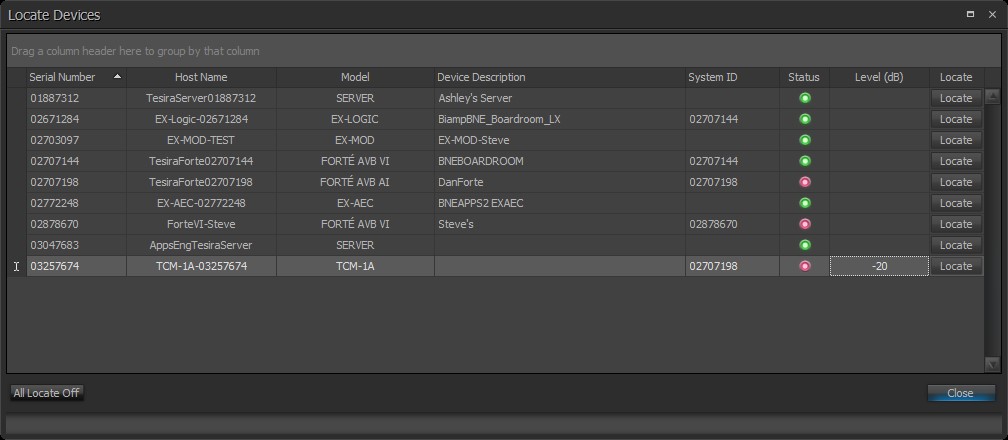
Locate Devices
The locate feature can be turned on or off for a device by clicking the Locate button within the Locate Devices dialog.
If multiple rows are selected and locate is clicked, the last-selected row’s value for locate is toggled and the other rows become unselected. For multiple selection Locate, a right-click context menu is available and has two options, “Turn on locate on selected rows” and “Turn off locate on selected rows”. These two options perform their given task on all selected rows.
The “All Locate Off” button will set locate to off for all devices (included the filtered out ones) in the list.
See the Locate Devices section for more details.
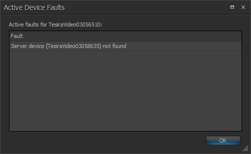
Faults
Faults displays a list of current faults on the selected device. Please see the System Status and Fault Reporting sections for more details. Devices may display sub-faults due to faults present in other devices within the same system. If the Faults option is unavailable this indicates the device does not have any current faults (also represented by a green Status indicator).
Retrieve Event Logs
Log files are stored by the Tesira software on a one file per device basis. The Retrieve Event Logs function allows the extraction of log files from a single server device. Functions include viewing logs as well as retrieving logs for saving on a local PC for offline review as a text file (.txt). If logs are required from all devices in a system they must be retrieved individually however using the Event Logs function in the System > Network menu allows a system wide retrieval of logs.
See the Event Log Overview section for further information.
Remote Devices
The Remote Devices function is used to display and manage remote device settings. These include such devices as audio expanders, controllers (HD-1, TEC-1, TEC-X 1000 and TEC-X 2000) and EX-LOGIC devices. See the Remote Device Maintenance section for more details.