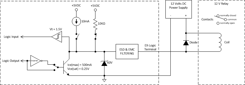
Logic IO Wiring
| 500ma transistor (pull down) | 10ma current source (pull up) | 10k pull up resistor | |
| Logic input | Always off | Always off | Always on |
| Logic output | Obeys logic state | Always off | Always on |
| Logic with powered output | Obeys logic state | Always on | Always off |
| Voltage Control | Always off | Always off | Always off |
Internal wiring
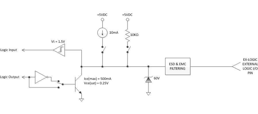
Wiring Volume Control
All potentiometers that are connected to the EX-LOGIC must be calibrated to ensure proper operation. See the TesiraFORTÉ, Server and SERVER IO Serial port settings EX Logic Serial Port Settings for more information.
Wiring a generic potentiometer
Wiring a potentiometer to an EX-LOGIC can be a bit confusing since it has three contact points. Not wiring it properly might cause the potentiometer to either work in reverse or not at all. Looking at the pot from the knob side with the contact points pointing at you, you will have the Low or CCW (Counter Clockwise) terminal on the left, the W (Wiper) terminal in the middle and the High or CW (Clockwise) terminal on the right. Connect the CCW terminal to the Ground terminal, the W terminal to the analog input and the CW terminal to the +5V terminal of the EX-LOGIC as shown in the diagram below.
A Linear-taper potentiometer in the 5K – 50K range is recommended. If a logrithmic (audio-tapered) potentiometer is used, the control will not seem to work “evenly” across the range. The inputs do have noise filtering but for longer cable runs, lower-value potentiometers in the 5K-10K range will have greater noise immunity.

Wiring the RP-L1 or RP-L2
The Biamp RP-L1 and RP-L2 are wall plates with 25KΩ linear taper potentiometers for volume control. The RP-L1 has only one potentiometer while the RP-L2 has two. These potentiometers come prewired from the factory with pigtails for ease of installation. These pigtails are color coded green for Low or CCW (Counter Clockwise) terminal, red for W (Wiper) terminal and white for High or CW (Clockwise) terminal. Connect the CCW (green) wire to the Ground terminal, the W (red) wire to the analog input and the CW (white) wire to the +5V terminal as shown in the diagram below.
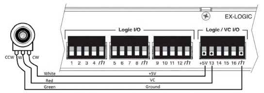
Internal Circuit
Wiring LED
Using EX-LOGIC as a power source
When configured as a logic output, each of the 16 GPIO pins can be configured as a current source to drive an LED directly (5V / 10mA maximum per output). To wire an LED in this mode, connect the LED’s anode (long lead) to the EX-LOGIC output and the cathode (short lead) to the ground terminal on the EX-logic as shown in the diagram below:
Using 'Enable Powered Output'

When using EX-LOGIC as a power source, the corresponding Logic Output blocks in your Tesira configuration must be created with the "Enable Powered Outputs" option selected.
Using External Voltage Source
Additionally, the GPIO pins 1-12 can be configured as simple contact closure outputs capable of sinking up to 300mA at 40V. In this mode, an external power supply is required (e.g. to drive a high brightness LED or multiple LED’s) GPIO pins 13-16 are not capable of sinking voltages greater than 4V and must use an external relay. Please note: When LED’s are wired to the EX-LOGIC using this method, the “Enable Powered Outputs” should remain unchecked in the Logic Output Initialization window in Tesira to avoid damaging the EX-LOGIC.
To wire an LED to an EX-logic using an external power supply, make the following connections as shown in the diagram below:
- Connect the negative terminal of the power supply to the ground terminal on the EX-LOGIC.
- Connect the positive terminal of the power supply to the resistor. Resistor value can be calculated using the following formula:
R = V/I
where:
- R = value of resistor in kOhms
- V = supply voltage – the LED turn on voltage
- I = required current in mA
- Connect the resistor to the LED’s Anode (long lead).
- Connect the LED’s Cathode (short lead) to the EX-LOGIC logic output.

Internal circuit
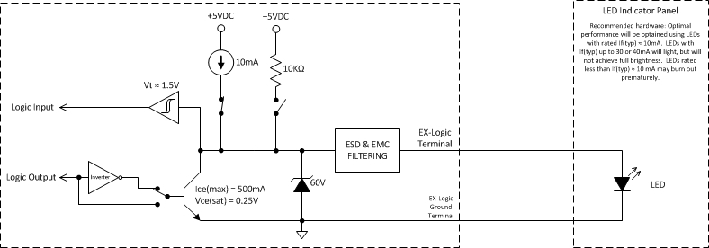
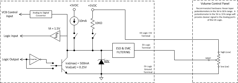
Wiring Relay
Wiring a relay is in essence very similar to wiring an LED. The only difference is that a resistor is not needed but a diode needs to be connected between the terminals of the relay coil to suppress high voltage transients that are generated when the relay turns off (Note that some relays have this diode already built-in). To wire a relay to the EX-LOGIC, do the following connections as shown in the diagram below:
- Connect the negative terminal of the power supply to the ground terminal on the EX-LOGIC
- Connect the positive terminal of the power supply to one of the relay’s coil terminals
- Connect the other relay coil terminal to the EX-LOGIC output
- Connect the diode’s Anode to the logic output of the EX-LOGIC
- Connect the diode’s Cathode to the positive terminal of the power supply

Internal Circuit
