Logic Output
Logic Output blocks accept logic signals which control the state of the corresponding Logic I/O terminals on a Tesira device.
Initialization Dialog
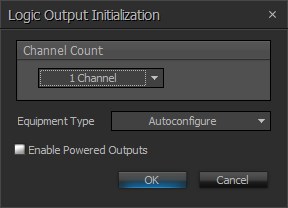
| Name | Description |
| Channel Count | The number of logic outputs to be added |
| Equipment Type | Specifies what type of hardware the Compiler should allocate the block to. Review the Equipment Type section for more details |
Enable Powered Outputs |
Logic Outputs can be configured to supply up to 10mA of current (at a voltage of 4.3 to 5 volts) to a connected device, which is intended to power an LED. In general, it is recommended that only one LED be powered from each logic output, as powering multiple LED’s from a single logic output may result in a significant reduction in LED brightness. |
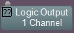
DSP Block Representation
If 'Enable Powered Outputs' has NOT been selected:
If 'Enable Powered Outputs' has been selected:

Control Dialog
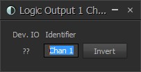
| Name | Description |
| Dev. IO | Displays the physical Logic I/O channel(s) on the Tesira device this block has been assigned |
| Identifier | Provides for a custom text label for the channel |
| Invert | Flips the function of the logic signal being accepted by the Logic Output block. When inverted, a Logic Output will open its output in response to a LOW logic signal, and it will close its output in response to a HIGH logic signal. |
Operation
When a Logic Output block receives a LOW logic signal, the corresponding logic output will “close” (i.e., the logic output will be shorted to ground, or more specifically, the voltage between the logic output and ground will be less than approximately 0.5 volts).
When a Logic Output block receives a HIGH logic signal, the corresponding logic output will “open” (i.e. the logic output will be open to ground, or more specifically, the voltage between the logic output and ground will be between approximately 2.7 volts and 5 volts).