Logic Input
Logic Input blocks generate logic signals depending on the state of external switches or devices that are connected to the logic inputs of a Tesira device.
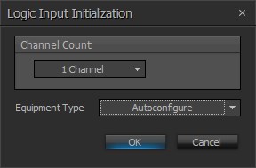
Initialization Dialog
| Name | Description |
| Channel Count | The number of logic inputs to be added |
| Equipment Type | Specifies what type of hardware the Compiler should allocate the block to. Review the Equipment Type section for more details |
DSP Block Representation

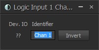
Control Dialog
| Name | Description |
| Dev. IO | Displays the physical Logic I/O channel(s) on the device this block is assigned |
| Identifier | Provides for a custom text label for the channel |
| Invert | Flips the logic signal being generated by the Logic Input block. When inverted, a Logic Input block will output a LOW signal when the input is open to ground, and a HIGH signal when the input is closed to ground |
Operation
The logic signal generated by a Logic Input block will be LOW when its corresponding logic input is “closed” (i.e., when the logic input is shorted to ground, or more specifically, when the voltage between the logic input and ground is less than approximately 0.8 volts).
The logic signal generated by a Logic Input block will be HIGH when its corresponding logic input is “open” (i.e., when the logic input is open to ground, or more specifically, when the voltage between the logic input and ground is between approximately 2.2 volts and 5 volts).