Logic Gate
Logic Gates are used to perform functions on logic signals. Logic signals can only be input and output from logic nodes, which appear on the top and bottom of component blocks.
A logic signal can only be in one of two states: HIGH or LOW (also commonly referred to as ON or OFF, 1 or 0, etc).
Logic Gates can perform various functions on incoming logic signals. The output of a Logic Gate depends on both its input and the type of Logic Gate that it is. Logic gates can be used in any combination to produce many varied behaviors, tables below summarize the function of each Logic Gate.
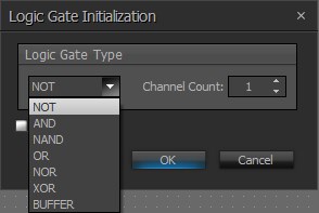
Initialization Dialog
Logic Gate Functions
NOT Gate

INPUT |
OUTPUT |
Summary |
HIGH |
LOW |
A NOT gate simply flips its input signal to the opposite state. Each individual input only affects its corresponding output. |
LOW |
HIGH |
AND Gate

INPUT 1 |
INPUT 2 |
OUTPUT |
Summary |
LOW |
LOW |
LOW |
An AND gate’s output will only go high whenever all of its inputs are high. Otherwise, its output will be low. |
LOW |
HIGH |
LOW |
|
HIGH |
LOW |
LOW |
|
HIGH |
HIGH |
HIGH |
NAND Gate

INPUT 1 |
INPUT 2 |
OUTPUT |
Summary |
LOW |
LOW |
HIGH |
A NAND gate’s output will only go low whenever all of its inputs are high. Otherwise, its output will be high. A NAND gate is a combination of a NOT gate and an AND gate. |
LOW |
HIGH |
HIGH |
|
HIGH |
LOW |
HIGH |
|
HIGH |
HIGH |
LOW |
OR Gate

INPUT 1 |
INPUT 2 |
OUTPUT |
Summary |
LOW |
LOW |
LOW |
An OR gate’s output will go high whenever at least one of its inputs is high. |
LOW |
HIGH |
HIGH |
|
HIGH |
LOW |
HIGH |
|
HIGH |
HIGH |
HIGH |
NOR Gate

INPUT 1 |
INPUT 2 |
OUTPUT |
Summary |
LOW |
LOW |
HIGH |
A NOR gate’s output will go high whenever at least one of its inputs is low. A NOR gate is a combination of a NOT gate and an OR gate. |
LOW |
HIGH |
LOW |
|
HIGH |
LOW |
LOW |
|
HIGH |
HIGH |
LOW |
XOR Gate

INPUT 1 |
INPUT 2 |
OUTPUT |
Summary |
LOW |
LOW |
LOW |
An XOR gate’s output will go high whenever only one of its inputs is high. For XOR gates with more than 2 inputs, the output will go high whenever an odd number of inputs are high. |
LOW |
HIGH |
HIGH |
|
HIGH |
LOW |
HIGH |
|
HIGH |
HIGH |
LOW |

INPUT 1 |
OUTPUT |
Summary |
LOW |
LOW |
The BUFFER logic gate is a pass-through block where the logic input and logic output is always the same value. This block is intended to be used with the TEC-1 to allow Logic priority for feedback. The circuits that include the buffer gate will not provide feedback to the TEC-1 screen. |
HIGH |
HIGH |